Turn a Fonera router into a link station
Inhaltsverzeichnis
- 1 Research first
- 2 Getting root access to the Fonera
- 3 Redboot
- 4 Flashing the Fonera
- 5 Compile the Flash image by myself
- 6 Configure the Fonera
- 7 Use DD-WRT in contrary to OpenWRT
- 8 Build a nice little case
- 9 Make some tests
- 10 Install a suitable Antenna
- 11 Tests
- 12 Firewalling
- 13 Future experiments
1 Research first
RTFM: Read the fucking manuals. Or the available documentation first. There's plenty of information out in the net, and here's a small compilation of links:
- http://db0fhn.efi.fh-nuernberg.de/doku.php#wireless_lan_hamradio - Janns pages on Amateur Radio WLAN (DG8NDN)
- http://wiki.openwrt.org/OpenWrtDocs/Hardware/Fon/Fonera
- http://sodoityourself.com/accessing-serial-console-on-the-fon
- http://jauzsi.hu/2006/10/13/inside-of-the-fonera
- http://www.dd-wrt.com/wiki/index.php/LaFonera_Hardware_Serial-Cable-Port
- http://www.flickr.com/photos/mother/261623405/sizes/o/
- http://www.larsen-b.com/Article/262.html
- http://wiki.cuwin.net/index.php?title=Flashing_the_La_Fonera_with_OpenWRT Excellent intro on flashing the fonera
- http://freethenet.scribblewiki.com/Merhaki Flashing a technically very related hardware
- http://sots.refuzed.org/?p=129&language=de Very cool: Upgrade the fonera by some SD Card storage (German)
- http://metalab.at/wiki/Fonera damn good Fonera hacking site
- http://www.neophob.com/serendipity/index.php?/archives/132-Using-Openwrt-on-La-Fonera-for-Dummies.html very good flashing instruction
- http://ecos.sourceware.org/docs-latest/redboot/redboot-guide.html Redboot User Guide
- http://www.fonboard.de/viewtopic.php?f=7&t=2229 Fonera mit OpenWRT 2.6 als WLAN-Bridge / AP nutzen - decisive tips!
2 Getting root access to the Fonera
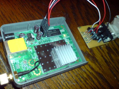
There are many ways to gain access to a router hardware. Some vendors provide a way to flash the router through an upload interface. Other vendors (like ASUS) provide a TFTP flash procedure. Most devices however somewhere have serial pins with which you can directly access a root shell. That's the case with the fonera router.
Nevertheless, you can't just connect it to the serial port of your workstation, because the voltage levels are different. You need to adapt the 5 V, or even 12 V from your computer to the 3.3 V on the device and vice versa. The 3.3V level is called TTL. For this reason I have built a level shifter, but you can buy ready kits from a multitude of vendors, also on Ebay.
But be careful you get the right converter chip! There are different versions, one for 5 V, one for 3.3 V. You definitely need the 3.3 V version.
Then start a minicom. Needless to say, forget WINDOWS on your workstation, since Hyperterminal isn't even part of VISTA any more. Hasta la Vista, baby. On linux, the package is called minicom. And you must make sure you configure the serial port correctly. Follow the instructions here:
- http://wiki.openwrt.org/OpenWrtDocs/Hardware/Fon/Fonera
- http://www.dd-wrt.com/wiki/index.php/LaFonera_Hardware_Serial-Cable-Port
Then replug the power cord and you can observe this:
+PHY ID is 0022:5521
Ethernet eth0: MAC address xx:xx:xx:xx:xx:xx
IP: 0.0.0.0/255.255.255.255, Gateway: 0.0.0.0
Default server: 0.0.0.0

RedBoot(tm) bootstrap and debug environment [ROMRAM]
Non-certified release, version v1.3.0 - built 16:57:58, Aug  7 2006

Copyright (C) 2000, 2001, 2002, 2003, 2004 Red Hat, Inc.

Board: ap51
RAM: 0x80000000-0x81000000, [0x80040450-0x80fe1000] available
FLASH: 0xa8000000 - 0xa87f0000, 128 blocks of 0x00010000 bytes each.
== Executing boot script in 1.000 seconds - enter ^C to abort

== Executing boot script in 1.000 seconds - enter ^C to abort

== Executing boot script in 1.000 seconds - enter ^C to abort
^C
RedBoot> ^C
RedBoot> ^C
RedBoot>
The RedBoot is kindof a BIOS and a good point to start flashing.
3 Redboot
Here is the right point to say some words about Redboot. Redboot is a mixture between a BIOS and a boot loader. To be exact, it is an operating system itself that is running before the kernel. As opposed to a 'real' operating system, it has only one application and only the fixed builtin commands. Yes, it does have an IP stack! You can retrieve files over it, using a number of methods such as TFTP and HTTP. But you can also use xmodem and ymodem. We're describing the usage of the tftp and http methods.
If you're using tftp, you need to have a TFTP server running on your workstation from which you're providing the images. If you're using http, you need a HTTP server on your workstation. Both methods serve to provide the according files to the Redboot client.
I will not explain how to set up a web server. There are many HOWTOs around in the internet, but on Linux, Apache is the webserver of your choice, because it is included in most distributions. As for TFTP, you need to install the tftp software package on your machine.
In case of TFTP, you follow the following steps:
cd $HOME   # yes, let's assume you're in your home directory.
mkdir tftproot
cd tftproot
wget http://downloads.openwrt.org/kamikaze/7.09/atheros-2.6/openwrt-atheros-2.6-root.squashfs
wget http://downloads.openwrt.org/kamikaze/7.09/atheros-2.6/openwrt-atheros-2.6-vmlinux.lzma
tftp 192.168.1.50   # we assume, the Fonera box will later work with this IP address during the installation.
                    # After entering this command we're in the tftp shell.
tftp> binary
tftp> trace
tftp> put <the filenames of the according files, see below>
Then you're set to enter the load commands in Redboot.
After everything is installed, and also in the normal boot process, Redboot starts a start script. We can have a look at the boot script with the command fcongif -l
RedBoot> fconfig -l
Run script at boot: true
Boot script:
.. fis load -l vmlinux.bin.l7
.. exec

Boot script timeout (1000ms resolution): 5
Use BOOTP for network configuration: false
Gateway IP address: 192.168.1.1
Local IP address: 192.168.1.50
Local IP address mask: 255.255.255.0
Default server IP address: 192.168.1.6
Console baud rate: 9600
GDB connection port: 9000
Force console for special debug messages: false
Network debug at boot time: false
RedBoot>
With fconfig you can set different values for the fields. I have modified mine, but be sure that the boot script is the one above. Especially if you change from DD-WRT to OpenWRT, the boot script is different. In the example above, we're booting the image vmlinux.bin.l7.
4 Flashing the Fonera
This site provides a number of ways to flash the fonera. I have copied the instructions from there since they worked fine for me.
Here's how I did it:
- I gained access into RedBoot through a serial console, so one step was done the easy way.
- Install a tftp server on my workstation and make the OpenWRT image available. I have taken the original image files for the first attempt:
- Tell RedBoot where to get the flash image from:
RedBoot> ip_address -l 192.168.1.50/24 -h 192.168.1.6
192.168.1.6 is the workstation with the TFTP server and 192.168.1.50 is the IP you're assigning to RedBoot.
- Initialize the flash partition table. This "frees" the usable flash space, between 0xA8030000 and 0xA87E0000.
RedBoot> fis init
- Load the root file system from the tftp server:
RedBoot> load -r -b 0x80041000 openwrt-atheros-2.6-root.squashfs
As an alternative, you can also choose the http method:
RedBoot> load -r -b 0x80041000 -m http -h 192.168.1.6 /fonera/openwrt-atheros-2.6-root.squashfs
- Write the root file system to flash:
fis create -l 0x06F0000 rootfs
You can calculate this value with "bc":
RedBoot> fis free
 0xA80F0000 .. 0xA87E0000
localhost:~# bc
obase=16
ibase=16
A87E0000 - A80F0000
6F0000
- Be patient this will take ~15-20m
- The FON will not respond to ping requests while writing to flash
- Load the kernel from the tftp server:
RedBoot> load -r -b 0x80041000 openwrt-atheros-2.6-vmlinux.lzma
Again, as an alternative if you want to get the image over http:
RedBoot> load -r -b 0x80041000 -m http -h 192.168.1.6 /fonera/openwrt-atheros-2.6-vmlinux.lzma
- Write the kernel to flash:
RedBoot> fis create -r 0x80041000 -e 0x80041000 vmlinux.bin.l7
- This can take a couple minutes
- Tell RedBoot which kernel to boot into:
RedBoot> fis load -l vmlinux.bin.l7
- Boot into the new system:
RedBoot> exec
- You may have to power cycle the FON
- Cross your fingers
When OpenWrt first boots, it formats the rest of the free flash space as a jffs2 filesystem. This might take a few minutes, so it's probably a good idea to let that finish before power cycling after the first boot.
If you leave the serial console attached, you can observe the entire process. After booting, you can also access the root shell directly through the serial console. OpenWRT will initially set the IP 192.168.1.1 unless you have configured the OpenWRT image compilation differently - if you have compiled your own image. After booting you should be able to telnet the Fonera at 192.168.1.1. But watch out! This is an IP which is frequently used by other routers as a default route. If you have your main router still rinning in the same network, there might be a conflict. So better unplug the main router :-)
5 Compile the Flash image by myself
I haven't gone so far yet, but that's possible off course. My general impression is that the precompiled images are fine enough. There are very few reasons to compile your own kernel. One reason is if you modify your own hardware and add some stuff like cardreaders etc. where you require additional kernel modules that need to be compiled.
6 Configure the Fonera
This setup describes the Fonera either as AP or as client. There is also a repeater mode, which is not described here.
6.1 AccessPoint configuration
This is fairly easy. You just need to open the file
/etc/config/wireless
and remove the line that says
option disabled 1
Then configure the "wifi-iface" according to your needs. Don't forget to set a specific "option ssid". Now reboot.
6.2 Client Configuration
This is also fairly easy. Open the same file. You also need to remove the "disabled" line. Then turn your attention to the "wifi-iface" line. Here you need to change the following things:
- set the "option mode" to "sta". This causes the Fonera to pick another WIFI station as AP.
- set the "option ssid" to the exactly the same as in your access point.
- on your access point, have a look at the MAC address of your AP with "iwconfig". Enter it as an "option bssid 11:22:33:44:55:66"
Now reboot.
For the other configuration options, have a look at the OpenWRT pages at: http://oldwiki.openwrt.org/OpenWrtDocs(2f)KamikazeConfiguration.html?highlight=(CategoryHowTo)
7 Use DD-WRT in contrary to OpenWRT
- 2009-12-21 I have decided to use DD-WRT instead of the above described installation of OpenWRT. The reason is that there is a so-called "superchannel"-license that permits the use of out of band frequencies in the B and G modes. So it is easily possible to configure the Fonera box to work in the Amateur bands and thus fulfil the requirements as defined by the Bundesnetzagentur.
- The Superchannel license costs 10 Euro per device and is thus reasonably cheap to stuff two of them. This is actually the last step to install a really official link between DB0MHB and DB0BUL, since only this license can guarantee that foreigners cannot hack our network and the HAMNET.
- I will need to replace the board that is already installed at DB0MHB on the rooftop.
- The DD-WRT installation is not really conplicated. There's only one single file that needs to be flashed ("linux.bin") and I decide to install it not via tftp but via http. See above. As level shifter I simply take my 3,3V programmer for Arduino boards.
8 Build a nice little case
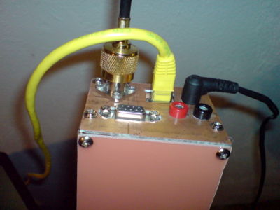
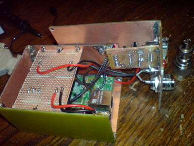
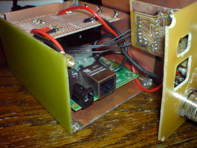
All these separate PCBs are just ugly. So I built a nice little and stable case to contain the level shifter and the fonera board. The PCB you see on top contains a DEMKE ELECTRONIC 311 DC-DC power converter so that I can connect the Fonera to a standard 12V (13.8V) line. The DC/DC converter can handle voltages between 7,5 and 40 volts, so there's plenty of room there. Setting up an entire alternative power supply network on 5V basis would be kindof unnecessary, but would also introduce possible risks because of unintentionally connecting 12V to 5V devices.
I have made good experiences with PCBs with copper on one side. They are excellent to solder and they are very stable. Together with a set of screws they can be mounted really professionally.
9 Make some tests
After having the entire assembly running for over a week now, I can say they're getting warm, but not excessively. The next big thing is to prepare them for the rough outdoor mission. For this purpose I will have to pick a suitable weatherproof case.
10 Install a suitable Antenna
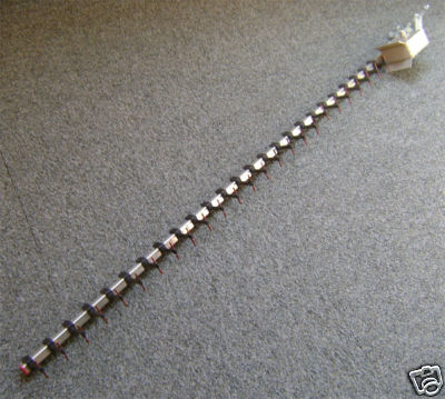
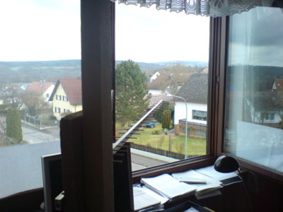
I have purchased a 25 element TONNA Yagi, 1.45 meters long. It has an excellent gain of 18,1 dBi. The antenna will be set up at DB0MHB. I will operate just a very small YAGI.
This antenna came from Ebay. It's an unknown brand. But it seems to work quite well.
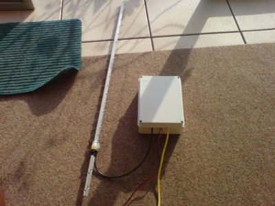
Here it is in a weather-proof case. In order to protect it from humidity, I simply tool a plastic spray and covered the board with liquid plastic several times. In addition to that, there's the PCB housing and there's also the weather-proof housing on top. It is important to mention that both cases are open to the bottom to allow for condensated water to flow out. It will be interesting to see how it can handle ice in winter times.
11 Tests
The above shown antenna setup works quite well. Have a look at my linking page of the other project:
Setting up a WIFI link between DL8RDS and DB0MHB
12 Firewalling
in order to forward packages, the following statments need to be stored in /etc/firewall.user
### Act as Router
iptables -A forwarding_rule -j ACCEPT

# Masquerade WLAN DHCP Clients
iptables -t nat -A POSTROUTING -s 10.2.25.81/28 -j MASQUERADE
where 10.2.25.81/28 is the source network. User defined rules can be stored in /etc/config/firewall or manually via uci. The syntax is very user friendy:
forward:<match>:<target>[:<port>]
      - Forwarding all packets to <target> (optional <port>), which match to <match>.

accept:<match>
      - allow all packets that match <match>

drop:<match>
      - drop all packets that match <match>
The options for <match>:
src=<ip>
      - source address <ip>

dest=<ip>
     - destination address <ip>

proto=<proto>
     - protocol name or number, for ex. "tcp" or "udp"
     If no protocol is given, anything will match.

sport=<port(s)>
     - source port(s) "22", "80,443" or "6667-6669"

dport=<port(s)>
     - destination port(s)
If you want to establish an ssh link over the WAN port (ethernet cable), set the following:
accept:proto=tcp dport=22
13 Future experiments
13.1 High Performance WIFI link
Yeah, I just bought a pair of 1 m diameter parabolic dishes and a couple of Mikrotik routers with 200 and 350 mW. As only for the antenna, hat will make not only 18 dBi but something around 22 dBi on each side.
I don't know how many milliwatts or dbM that will be, but sure a lot.
Calculations according to: http://home.in.tum.de/~prilmeie/wlan/db-umrechnung.xhtml
13.2 Forward the serial port over the LAN
ser2net seems an interesting way to go.
- http://www.nwlab.net/tutorials/ser2net/konsolenserver-linux.html
- http://forum.openwrt.org/viewtopic.php?id=13161
13.3 Provide some storage
And to complete all this madness, there are nice plans around in the net how to upgrade your Fonera into a little kind of a server. Therefore you need storage, and yes, there are unused GPIO pins on the Fonera board. Here's a collection of links that provide the necessary knowledge.
- http://wiki.openwrt.org/OpenWrtDocs/Customizing/Hardware/MMC - general GPIO / MMC information
- http://fghhgh.150m.com/ - a driver for GPIO
- http://www.fonboard.de/viewtopic.php?f=7&t=1945 - an extensive discussion with lots of info
- http://www.dd-wrt.com/wiki/index.php/Fonera_SD-Card_hack - great info, here for DD-WRT
I haven't started this yet, and I'm unsure if I'll ever start this, because the constellation is fine like this. But maybe some of you find these ideas inspiring :-)
