A Low-Power Combined Echolink and ATV Server
Inhaltsverzeichnis
1 Project Overview
Things evolve, and after initial attempts to set up an Echolink relay on basis of OpenWRT, I decided that porting the SVXLink software is a little too time-consuming. And since Intel's ATOM CPUs are available now, it seems reasonable to choose one of those and charge the machine with some more jobs. For this reason, I decided to build some hardware for this scenario:
- act as an Echolink node to let me speak to my buddies from DB0MHB on our working frequency 144.510 MHz.
- record video transmissions from DB0MHB, convert them into something you can stream over the internet and act as a streaming server.
- provide mass storage and act as a playout server for ATV.
- consume as little power as possible to allow permanent cost-efficient operation
This project is a supertarget of the following projects / items, while absoleting some of them.
- Setting up a remote, electrically independent, low power EchoLink relay
- Porting SVXLink to OpenWRT - given up. Using standard Linux instead.
- Building a Linux Ubuntu package of TheLinkBox
- Compiling a TheLinkBox package for OpenWRT - obsoleted
- Compiling a Hamlib package for OpenWRT - obsoleted
It makes use of the following hardware:
- Kenwood TR-7625
- BX-120 Transceiver Interface
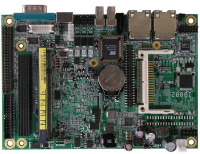
- IB882-16
- Hauppauge USB-PVR2
- WIMO ATV receiver board
- WIMO ATV transmitter board
Just for completeness, some more interesting articles:
2 Hardware
2.1 CPU Unit
First measurements show that the IB882 using the 530 series Intel ATOM CPU is power-saving, but less than you'd expect. Marketing people said that the power consumption was just at around 4 watts, but this is probably only true for the CPU itself. The rest of the board also consumes some power, and that's quite a bit more than the CPU itself. I measured a current of around 1 Ampere, making about 13,8 Watts total. This, given that the Hauppauge PVR is not yet connected!
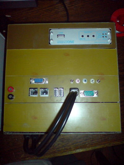
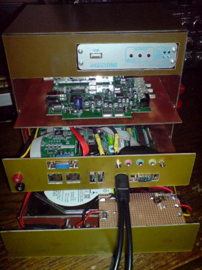
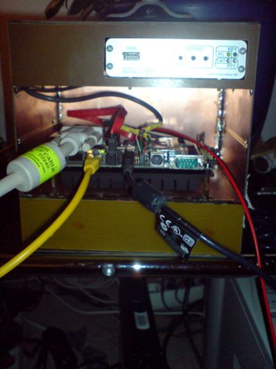
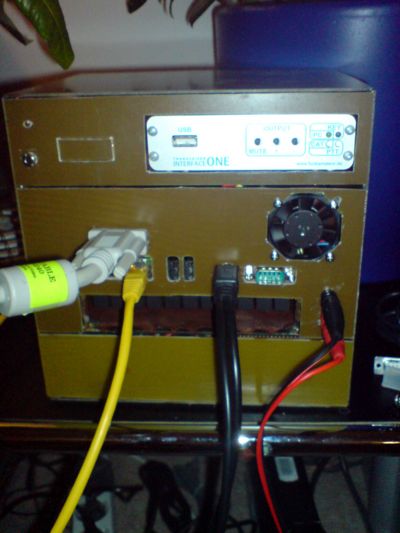
At least, I already built a nice case that will hold the boards. This time, I didn't build a single case for each board, but since several components demanded some housing, I decided to build a big case for four components at a time. In order to keep everything modular and support easy maintenance, I used small U-profiles from RC model construction that allow me to slide the boards in and out. Here are some photos. On the first photos, the connections are not yet completely ready. I still need to drill some holes and attach some sockets.
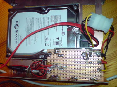
The lower right picture shows the hard disk cage from inside. The striped PCB covers a Cosel DC-DC-converter from 12V to 5V. Since I do not expect to receive an exact voltage of 12V according to the ATX specification here, I am operating two 78S12CV in parallel, which are soldered right onto the drawer, but which are invisible because they are under the Cosel board.
As said, things evolve, and Spectra has sent me a heat sink, because the little board does indeed generate some heat. After the insight that the sink must not reside just on the PCB, but that there must be some circulation below, I understood that the SDIO graphics board will no longer fit in. Either I would have a computer without VGA or a computer box with VGA but without one of the boards on the above photographs.
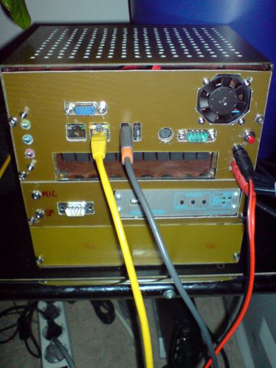
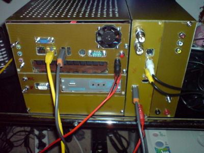
I decided against the Hauppauge board and in favour of the VGA interface, and also in favour of some more sockets on the front panel. Now the hard disk drive is in the lower bay, the transceiver interface is in the upper and the computer resides in the middle.
Here's an overview of the power consumption at 13,8 volts:
2~   A    disk spin up, very short
0.7  A    disk running, computer off
1.8  A    computer running, disk running
1.26 A    computer running, disk put to "sleep" mode
That is still 17,3 Watts with the disk set to sleep. More than I had expected. And it will be 152 kWh per year. That will mount to costs of about 23 Euro per year with an assumed price of 15 ct per kWh.
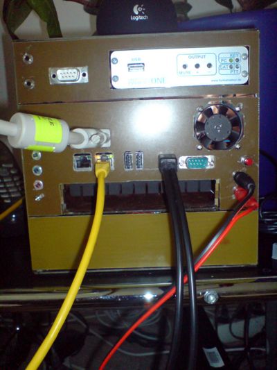
Please also notice the fan in the right upper corner of the central front panel. It's a 40x40 mm Pabst fan which is driven by a heat-controlled logic and comes up whenever it's becoming too hot within the case. This is only the case when I'm compiling stuff. When the hard disk is sent to sleep, it never comes up. But it is fantastic to see how this fan goes on and off during kernel compilation. Oh, yes, I admit, the octagon for the fan is not so regular after all. I didn't have so much time to measure it precisely. In the end, it works.. and that's what counts here.
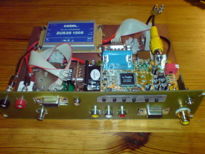
The above photographs show the development of the front panel and the entire setup. The rightmost image shows the device as it is complete: It now has the connections for the radio on the upper drawer (2x 3,5 mm jacks, as said above a SubD-9 socket), the sound card jacks, and also the power button on the right hand side.
And please also note the holes on the top cover. I drilled them to support the dissipation of some heat. And please also note that the CPU unit has moved up. It's because of the concentration of heat-generating components on the lower half of the case: CPU and hard disk. Now these components are separate and there's no longer a cluster of heat in the middle. Also, with the upper case ceiling the CPU unit now has another external board through which heat can dissipate easier.
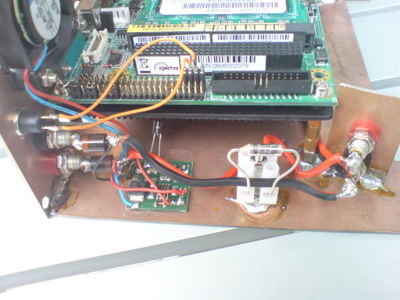
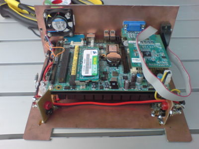
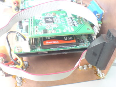
Images above:
- left: Here you see the electrical management: The power comes in, goes through the diode(s). Then it drives the temperature controlled fan. Then (red wire) it goes into the temperature fuse. And then it goes into the device. The power sockets have two diodes, grace to my paranioa. The temperature fuse blows up at 72° degrees Celsius. It should never become so hot at the outer side of the case. If so, there's something essentially wrong and high time to cut the electricity.
- center: That's the cpu component from behind. Lower left and lower right you see electricity ports that can feed other components within the same case (such as the hard disk).
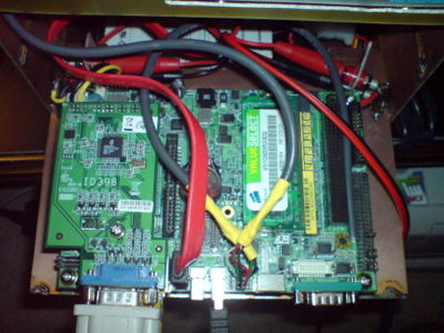
- right: That's the cpu board from the right hand side. You see the CF slot and the socket for the audio.
2.1.1 Connectivity
In order to connect the transceiver interface to the radio rig, I refer to the C5 standard:
- http://www.chaoswelle.de/CCCCC Chaoswelle Contest Crew Compatible Cabling
Stecker D-Sub 9 polig
pin 1 Ohr links
pin 2 Masse Ohr links
pin 3 Ohr rechts
pin 4 Masse Ohr rechts
pin 5 Masse PTT
pin 6 Mikrofon
pin 7 Masse Mikro
pin 8 +8V (Wenn verfügbar)
pin 9 PTT
Buchse am TRX, Stecker am Headset
In my scenario, I will mount two sockets to my upper section that carries the transceiver interface. One socket will go to the microphone input of the TRX, the other will go to the loudspeaker of my rig.
2.1.2 Boot Architecture
I managed to get Ubuntu Hardy 8.04 running and booting from my flash disk. It's a 8 GB flash disk that should provide enough space to home all sorts of data. Today (26.06.2009) I also purchased a 1,5 Terabytes hard disk that will serve as storage. Once the operating system is really really complete and there's nothing that needs to be added, I will create a real read only boot system based on something like UnionFS. It's like those bootable KNOPPIX CDs.
2.2 Video Receiver Unit
Mainly for heat dissipation reasons I was forced to ban the frame grabber from the main case. So there was the need to build a second case that holds all the video components. I decided to place a WIMO ATV receiver right into the same case to have all the devices together that act on the same class of signals.
The images above:
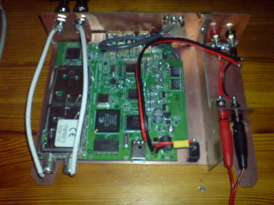
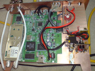
- upper left is the Hauppauge USB-PVR2, yet without the Cosel voltage regulator. My first experiment with a parallel arrangement of 78S06 voltage regulators was not successful, because they got awfully hot,even in parallel. I was already suspicious that some of them were broken, but apparently that's common to the 780x series. I didn't want to have another temperature problem: These devices are meant to run without surveillance, and I cannot afford to operate a potential source of fire. The original power supply delivers 6V at about 1.66 Amps. 6V is a really stupid voltage for DC/DC pulse width DC converters, because there does not seem to be anything on the market which produces 6V out of 12-13V with a fairly good degree of efficiency. The deliver 3.3, 5, 12 and 15 volts. but nothing in between. Some can be trimmed a little, but not substantially. So I was left to try out if the device can be operated on 5V as well. I have made good experiences with the COSEL ZUS251205. They don't get hot and with the really oversized spec of 25 watts, I don't risk to overcharge anything.
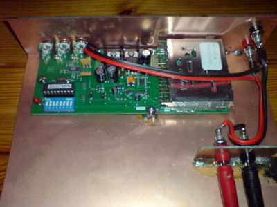
- upper right is the ATV receiver from WIMO: http://www.wimo.de/atv-baugruppen_d.html Since DB0MHB transmits on 1280 MHz, this device seems well fit. I still cannot say for sure if I need to modify it a little, but according to the mods instructions (which come with the device thanks to WIMO) this doesn't seem a really difficult task either. Note that every component has a port for internal voltage, so there's no need to connect all the components within one case. All the components are secured from false polarity connects by really huge diodes.
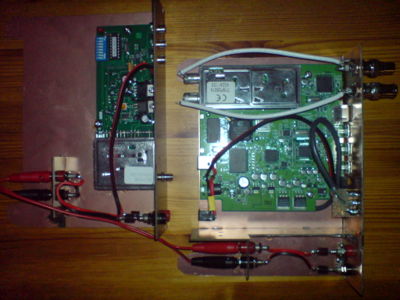
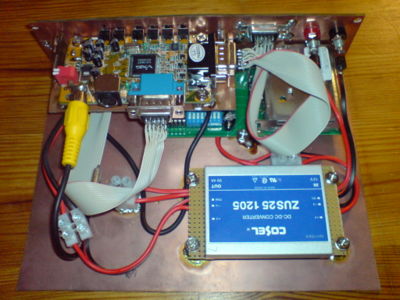
- lower left shows all the components of the video case connected to another. There's still one modification I still want to apply: It is kind of annoying and also unnecessary in my eyes to connect the video channels over the front plates. For this reason I want to create another port inside of the case. Well, as said, the COSEL is still missing on that picture.
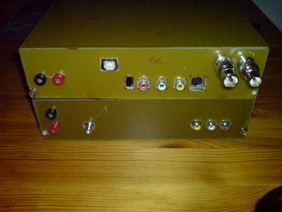
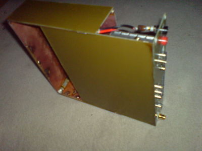
- lower right: the entire case from the front side. Note that I have installed 75 Ohm BNC sockets for TV and BC in. In front of them there are two converters. I like BNC more than the traditional plugs. They seem more solid to me... Please note that I led the USB socket from the rear end of the PCB to the front panel, and I just soldered a USB cable onto the on board socket. I first tried to remove the socket from the board but then was too afraid to ruin something. The tiny SMD things probably won't stand brutal heat from my soldering iron... So I tried to find out which pin is which signal and extended it...
- http://www.hardware-bastelkiste.de/index.html?usb.html has some excellent explanations on USB cabling.
Ah, yes, some screws are still missing on the front panels...
The above picture shows the Hauppauge component with the Cosel ZUS 251205 built in. And yes, I was surprised indeed, because the Cosel allows to trim the output voltage, not just by the 5% up or down, but far more. I found out that if you put a resistor of 1 kOhm between output V- and the TRM pin, you can tune the voltage to around 5,8 volts, which is perfectly sufficient for this device. By now you can also see the internal video connect between the two boards in the video unit.
A final praise: I really love DREMEL. I bought the Dremel 400i Digital, and it helped me tremendously. Drilling all these holes and cutting smaller pieces of PCB is just hell without such a fine tool. I love precision and control over my tools. And the Dremel 400i delivers just that. Especially the drill extension is fantastic. It's a 140 watts engine, but you can hold it like a fine pen. Well, nevertheless it sometimes escaped, which you can see by the scratches on the PCBs, but function rules over beauty anyway ;-)
2.3 Video Transmitter Unit
The Video Transmitter combines two devices in one case: A VGA-PAL converter and a WIMO ATV transmitter module. Actually, there's nothing special about this device. Again, I used a COSEL DC converter to transform the 12V down into a stable 5V to run the PAL converter. Actually, it's like shooting sparrows with cannonballs, because the COSEL is vastly and generpously oversized compared to the current which is really required. But I prefer oversized electronics. It won't be hot after all.
This time my case design has taken another evolutionary step: I developed a case design that does no longer require an extra carrier board inside, but uses U profiles to slide the carrier board into the cover.
2.4 Uninterrupted Power Supply
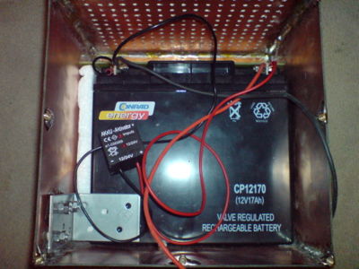
A thunderstorm some weeks ago did the unthinkable in our modern world: It caused the power grid to break down. Presumably some trees had fallen on overland lines, but in any case, every electrical device in our house was dead. This ignited some ideas in my head how to protect my machinery from power outages. Since I didn't see a good reason in commercial UPS's practice of transforming 230V down to 12V, back up again into 230V to leave the UPS. And then down again to 12V to feed my server, I thought about introducing some buffering capacity in the final 12V circuit. Here it comes...:
- The core is a 12V, 17Ah lead accumulator.
- A battery activator which destroys sulfite crystals which may form when the accumulator is rather passive.
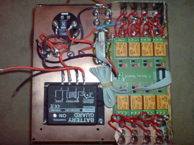
- A battery guard which prevents deep discharge.
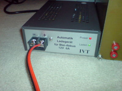
- A constant current charger that acts as a power supply in the regular case and charges the battery in case its internal voltage is below the charging voltage. I regulated the charging voltage to 13,50 volts to prevent gassing caused by overcharging.
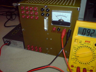
And here is the entire assembly. You can see, it's still charging, but the accu is nearly full.
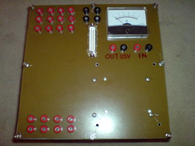
The many sockets and the PCB which you see on the rear side of the panel have an interesting purpose, too. Since there is the central CPU unit, but also some other units like the video RX unit, and the video TX unit as well as the Echolink TRX, it should be able to switch them on and off from remote. The upper number of sockets privides for such a facility, and the lower array of sockets is just for closing circuits. The upper array also serves for interrupting normally connected circuits. There is a total of 8 relays on the board which all allow to switch from normally connected to normally disconnected states.
The connection below the meter which reads "USV OUT" is connected to the meter. The current range is up to about 5-6 Amps, because this is also about the ultimate maximum what the central processing cube roughly consumes - given that there are some more modules that need to be run. Basically, the entire system can support currents of up to 20 Amps for a short time, 10 Amps preliminary and 5 Amps on a constant basis. From a recharging cycle that went rather deep, I have seen that 20 Amps is not really healthy for the wiring, because even the 2,5 mm² cables are getting hot. This is something that should actually not happen.
In the near future I will add a fuse to the connection between accu and battery guard and perhaps also a temperature fuse. I still don't know for which current the temp fuse is rated, because the legs of the device are not tremendously thick. But I am sure to find out :-) Let it be by experiment...
2.5 Recent Developments
- 2009-11-10 I decided not to use the hard disk in the bottom drawer but to leave it empty. The reason is that
- a) the device itself should consume as little power as possible in order to reduce heat to a minimum
- b) I have seen that the ATX specifications are extremely narrow and leave little room for under / overvoltages. In other words: I ruined a hard drive.
- c) I have now purchased a Synology NAS which will provide enough disk space for any future storage problem.
- 2010-06-28 I decided to place a backdoor GSM dialin system into that tray which has been empty for the described reasons:
- 2010-08-15 I decided to redesign the case of the framegrabber unit because the USBPVR-2 consumes quite some power and the Cosel converter became quite warm. For that reason I decided to use a 3 story case and use a bigger DC converter that will not get warm at all and has some cooling structures built on it. Now really everything works fine.
- I have also decided not to use the transmission module in this context because we can now transmit using the beagleBoard which is directly atached to the DB0MHB relay station. Since we have a fantastic WIFI link between the stations, we can stream the signal if desired.
3 Software
3.1 Operating System
The device runs on the most recent (2.6.30.1) Linux kernel. The default kernel as delivered by Ubuntu Hardy was not appropriate for various reasons: It caused problems in a scenario where the device would boot from a flash disk and then mount a SATA disk. Maybe I had been able to fix that too with the older / original kernel after some more research, but for convenience reasons I decided to give it a try with the newest release - and it worked. Another advantage of running a self-compiled kernel is that I was able to decide which kernel module would go into it and which not. My embedded hardware has various features (like a watchdog) that are supported by the kernel but for which the modules are not on the standard distribution. On the other side, the embedded hardware is not likely to change in the next years, so it was not necessary to store a great number of modules for which I am not planning to buy devices.
I also had problems with the ethernet port: The standard kernel 2.6.24 didn't support the Gigabit Ethernet device properly, so I initially had to compile my own network card driver. The new kernel didn't have these problems.
In general you can say as a rule of thumb: If you run the really most recent kind of hardware, it's wise to use the most recent kind of kernel, too.
For Debian-like distributions, there's the kernel-package software package. It contains all sorts of stuff, especially a fantastic tool calles make-kpkg, which produces a debian package right out of a linux kernel source tree. You start it with
/usr/src/linux $> make-kpkg kernel-image
and then the according *deb files will be generated into the directory "/usr/src". You can install them with
/usr/src $> dpkg -i linux-image-2.6.30.1_2.6.30.1-10.00.Custom_i386.deb
3.2 Other Hardware Drivers
In order to run the Hauppauge USB-PVR2, it was necessary to include some kernel modules and some other code.
Firstly, v4l-2 support must be compiled into the kernel.
At least, the appropriate modules must be there.
Since the Hauppauge card has a Conexant chip on board, it requests some special firmware driver upon USB initialization. You have to provide that code by copying some files into /lib/firmware. I downloaded the firmware drivers from http://ivtvdriver.org/
Ubuntu also has a package: ivtv-utils This package provides the tools to switch input channels on the Hauppauge card.
3.3 Applications
- SVXLink
- I needed to compile it from gound up, but that's not so difficult as it seems. The only really annoying thing is that you can't be sure right away that all your requirements are fulfilled. There are some libraries here and there that need to be installed. And I needed to create a special start script. I think, I'll really port it to Debian. For documentation and further info look there:
- http://www.dc5mn.de/?Echolink_SvxLink:SvxLink_Anleitung
- http://www.firma-kct.com/cgi-bin/show.pl?page=SvxLink-Tips
- video streaming
- Martin Dauskardt has sent me some hints:
- The frame grabber I used is a Hauppauge USB-PVR2, which is fairly well supported on Linux. As said, for diverse reasons I had to put it into an external case, but that's not so bad either. When connected via USB, given that the necessary drivers and the firmware has been loaded, I can simply issue the following commands
$> v4l2-ctl --list-inputs -d0  # this will give me all the input channels for the card
ioctl: VIDIOC_ENUMINPUT
       Input   : 0
       Name    : television
       Type    : 0x00000001
       Audioset: 0x00000000
       Tuner   : 0x00000000
       Standard: 0x0000000000000000 ( )
       Status  : 0

       Input   : 1
       Name    : composite
       Type    : 0x00000002
       Audioset: 0x00000000
       Tuner   : 0x00000000
       Standard: 0x0000000000000000 ( )
       Status  : 0

       Input   : 2
       Name    : s-video
       Type    : 0x00000002
       Audioset: 0x00000000
       Tuner   : 0x00000000
       Standard: 0x0000000000000000 ( )
       Status  : 0

       Input   : 3
       Name    : radio
       Type    : 0x00000001
       Audioset: 0x00000000
       Tuner   : 0x00000000
       Standard: 0x0000000000000000 ( )
       Status  : 0

$> v4l2-ctl --set-input 1 -d0  # this will set the input to composite video
and when I now connect a little camera to the composite interface, I can very easily produce an MPEG-encoded movie.
$> cat /dev/video0 >> /home/movie.mpg
The same works with the input source nr. 0 (television) with which you can record TV movies. But we're not doing TV experiments. Instead, we're interested in ATV streaming.
Have a look here: http://forum.ubuntuusers.de/topic/ich-will-hauppauge-wintv-pvr-usb2-unter-hardy/
But what I finally want is to stream a real picture. The application "vls" is good for that:
The config for vls is this:
# vls.cfg (VLS configuration file)
# Example of the VideoLAN HOWTO for Hauppauge USB-PVR2 encoding cards

begin "inputs"
 pvr0       = "video"
end

begin "input"
 trickplay = "normal"
end

begin "pvr0"
 # This card is a Hauppauge USB-PVR2
 cardtype      = "pvr"
 # Device name
 device        = "/dev/video0"
 # Stream type
 type          = "mpeg2-ps"
 # Norm: put "pal", "secam" or "ntsc"
 norm          = "pal"
 # Framerate: put "30" for NTSC and "25" for PAL and SECAM
 framerate     = "25"
 # Input number: put - "0" for Composite on S-video plug
 #                    - "4" for tuner
 #                    - "6" for S-video on S-video plug
 inputnumber   = "1"
 # If you use the tuner, put the frequency
 frequency     = "567250"
 # Image size: put "widthxheight" or "subqcif" (128x96) or "qsif" (160x120)
 # or "qcif" (176x144) or "sif" (320x240) or "cif" (352x288) or "vga" (640x480)
 size          = "720x576"
 # Bitrate in Kbit/s
 bitrate       = "7000"
 # Maximum bitrate in Kbit/s
 maxbitrate    = "9000"
 # Bitrate mode: put "cbr" (constant bitrate) or "vbr" (variable bitrate)
 bitratemode   = "vbr"
end

begin "channels"
 channel1       = "network"
end

begin "channel1"
 # Unicast or multicast IP address
 dsthost = "192.168.178.27"
 # Destination port
 dstport = "1234"
 # If it's a multicast IP address, uncomment the line below
 #type    = "multicast"
 # If it's a multicast IP address, set the "Time To Live" below
 #ttl     = "12"
end

begin "launchonstartup"
 command1 = "start video channel1 pvr0"
end
Then simply start vls with this command:
$> vls -vv -f vls.cfg
Once everything is fine, you can omit the "-vv" since it just controls verbosity.
More information is there: http://www.videolan.org/doc/videolan-howto/de/ch07.html
3.4 Setting up audio
Once again, it is recommendable to follow the instructions given here:
4 Operation
4.1 USB Video Streaming
Works fine.
mjpg_streamer is a great program. At least, it produces a new image upon request. I haven't gone further yet, but at least, the pictures are available on a web browser which does not require special software on the client side. VLC might be capable of displaying the entire stream as such, but I haven't tried this.
4.2 Composite Video Streaming
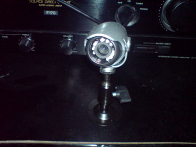
With VLS as the streaming tool and VLC as a streaming client, that's just excellent. I am using a little infrared enabled camera to generate a signal. It's just fantastic!
4.3 ATV playout server function
This feature is not yet implemented because it takes some decisions on how to receive and process the movie signal also on the DB0MHB side.
4.4 ATV Streaming
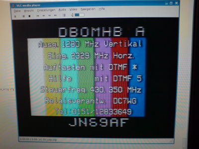
2009-08-09: It works! The ATV receiver board required some slight modification. I had to replace the SFE 6,0 MHz filter by a SFE 5,5 MHz one. Last night I was able to verify that the receiver board does ideed process the DB0MHB video signal. And that the Hauppauge board does indeed process and encode the signal stream.
The only observation made in this context is that the stream is rather voluminous. Over a local network, it is easily possible to transport a full size PAL video stream, but in order to use the upload speeds available in the region, it is vital to reduct the picture in many aspects: Make it simply smaller, reduct color depth, reduce frame rate. Let' see wich results I will archieve.
4.5 Echolink
- 2009-07-02 As of today I have applied for a test callsign with which I can then operate my little device. Let's see what the federal networks authority (Bundesnetzagentur) is saying.
- 2009-07-18 Today I have set up the box at the final destination in Burglengenfeld. There I have configured it accordingly, defined the port forwarding for the Echolink ports and everything. Time was too short to try it out on my transceiver, but I see that the node does appear in the Echolink node list. And I can connect to it, which is a brilliant success for today. It sends me the boring standard SVXLINK welcome message. Will need to replace this. The only step left is to make sure that the node can really control my rig. But also as for today I kind of found out how about the wiring of that weird microphone plug... It's a 4 pin 1980s Japanese plug, and it is like this:
pin 1 - signal from the microphone
pin 2 - PTT. Switches when connected to GND.
pin 3 - GND
pin 4 - GND
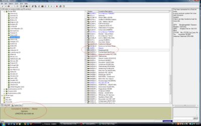
- Here's my screenshot. I can see myself twice (no, I am not drunk :-) One entry is DL8RDS, which is me right now sitting in front of my laptop here in Munich, and the other is DL8RDS-L, which is my SVXLink node in Burglengenfeld. At the bottom you can see that I'm currently connected to my machine.
- If you want to check if the node is registered and "on", have a look there: Search for "DL8RDS-L" http://www.echolink.org/logins.asp
- 2009-07-20 Today I was able to verify that the transceiver control basically works: Whenever I connect and the welcome message comes up, and when I click the space bar / PTT switch on my keyboard, the PTT and KEY LEDs come up. So basically, the PTT switching should be OK.
- 2009-08-25: My License assignment document has arrived! From now on, I am officially permitted to operate DB0BUL-L as an Echolink Link server on 144.975. Have a look here: http://www.echolink.org/logins.asp Yet, the radio is not connected to the computer, but the logon procedures should already work.
