High Performance WIFI link: Unterschied zwischen den Versionen
Dl8rds (Diskussion | Beiträge) (→Installation) |
Dl8rds (Diskussion | Beiträge) (→Installation) |
||
| (23 dazwischenliegende Versionen desselben Benutzers werden nicht angezeigt) | |||
| Zeile 1: | Zeile 1: | ||
[[Image:Schuessel.jpg|400px|right]] | [[Image:Schuessel.jpg|400px|right]] | ||
[[Image:MikrotikRB433.jpg|400px|right]] | [[Image:MikrotikRB433.jpg|400px|right]] | ||
| + | [[Image:mikrotik-gehaeuse1.jpg|400px|right]] | ||
| + | [[Image:mikrotik-gehaeuse2.jpg|400px|right]] | ||
== Project goals == | == Project goals == | ||
| Zeile 85: | Zeile 87: | ||
1 8 ---DCD--' `--DCD------- 8 1 | 1 8 ---DCD--' `--DCD------- 8 1 | ||
| + | |||
| + | The speed is 115200 bit/s and the login credentials after a fresh installation are '''admin''' and no password. | ||
=== Pick an operating frequency === | === Pick an operating frequency === | ||
| Zeile 91: | Zeile 95: | ||
I decided to pick the following frequencies for the link experiment: | I decided to pick the following frequencies for the link experiment: | ||
* DB0MHB side | * DB0MHB side | ||
| − | ** | + | ** 2392 MHz RX |
** 5680 MHz TX | ** 5680 MHz TX | ||
* DL8RDS side | * DL8RDS side | ||
** 5680 MHz RX | ** 5680 MHz RX | ||
| − | ** | + | ** 2392 MHz TX |
=== Pick IPs === | === Pick IPs === | ||
| Zeile 105: | Zeile 109: | ||
=== Ring Exciters === | === Ring Exciters === | ||
Antenna construction is probably most visible engineering effort in the entire project. We are constructing a weatherproof pair of concentrical ring exciters for the focus of the dishes. | Antenna construction is probably most visible engineering effort in the entire project. We are constructing a weatherproof pair of concentrical ring exciters for the focus of the dishes. | ||
| + | Here's some theory... | ||
| + | |||
| + | * http://www.w1ghz.org/antbook/chap11.pdf Paul Wade. The W1GHZ Online Microwave Antenna Book. Chapter 11. 2006. - Excellent explanation on possible causes for gain loss in a parabolic scenario. | ||
| + | * http://www.mydarc.de/dj6iy/ghz-antennen/ghz-ant.html | ||
| + | * http://www.antennex.com/w4rnl/ | ||
| + | |||
| + | And some practical guidance: | ||
| + | * http://www.dd7mh.de/RingPraesentWeb/img0.html Ring Exciters from Hans DD7MH | ||
| + | |||
| + | And some print literature: | ||
| + | |||
| + | * S. Silver. Microwave Antenna and Design. McGraw-Hill, 1949. pp. 239 - 256. | ||
| + | * M.W. Dixon, G3PFR. Microwave Handbook. Volume 8. RSGB, 1992. p. 14.25. | ||
| + | * R. Sletten, KB1QV, C. Sletten, W1YLV. "An Efficient Feed for a 12" EME Dish". Proceedings of the Eighteenth Eastern VHF/UHF Conference. ARRL, 1992. pp. 67 - 70. | ||
| + | * D. Turrin, W2IMU. "Antenna Performance Measurements". QST, Nov 1974. pp. 35 - 41. | ||
| + | * EIA Standard RS.329. | ||
| + | * D. Turrin, W2IMU. "Parabolic Reflector Antennas and Feeds". The ARRL UHF/Microwave Experimenter's Manual. ARRL, 1990. p. 9 - 35. | ||
| + | * J.E. Pearson, KF4JU. "Modified Feed Antennas for Parabolic Dishes". Proceedings of Microwave Update '91. ARRL, 1991. pp 194 - 204. | ||
| + | * B. Larkin, W7PUA. "Dipole-Reflector Parabolic Dish Feeds for f/D of 0.2-0.4". QEX, Feb 1996. pp. 3 - 11. | ||
| + | |||
The perimeter of the ring is 1 lambda (1 full wavelength). We calculate the wavelength with the formula | The perimeter of the ring is 1 lambda (1 full wavelength). We calculate the wavelength with the formula | ||
| Zeile 125: | Zeile 149: | ||
* r = 8.28 mm for the 5.2 cm ring for 5680 MHz | * r = 8.28 mm for the 5.2 cm ring for 5680 MHz | ||
| − | Hey, that's pretty small....! | + | The distance d to the reflector should be 1/8 * lambda, so |
| + | |||
| + | * d = 1.575 mm for the 12.6 cm ring for 2380 MHz | ||
| + | * d = 0.650 mm for the 5.2 cm ring for 5680 MHz | ||
| + | |||
| + | Hey, that's all pretty small....! | ||
The exact length if the ring wires can be measured with a SWR meter / reflectometer that can determine the resonnance point of the antenna by comparing the fed and the reflected HF energy. You generally iterate over a frequency spectrum and measure some SWR values. Then you draw a graph. There should be a minimum at some point, but with overlengths the minimum should be below your target frequency. Now we can shorten the antenna until we have a perfect match at the operating frequency of our intention. | The exact length if the ring wires can be measured with a SWR meter / reflectometer that can determine the resonnance point of the antenna by comparing the fed and the reflected HF energy. You generally iterate over a frequency spectrum and measure some SWR values. Then you draw a graph. There should be a minimum at some point, but with overlengths the minimum should be below your target frequency. Now we can shorten the antenna until we have a perfect match at the operating frequency of our intention. | ||
| Zeile 132: | Zeile 161: | ||
=== Cases === | === Cases === | ||
| − | + | The cases are ready. I have built two cases for each Mikrotik board. The cases have consumed some thought, especially on how to make them weather-proof. I got inspired by the design of SSB's preamplifiers: The board carrier PCBs slide into the case from the bottom and are led by U profiles. The carrier board doesn't just slide in to shut the case but goes in a centimeter deeper to provide a drain ridge so the rain drops won't flow into the case. And finally, the current setup allows very easy sealing. Here are some photographs: | |
| + | |||
| + | [[Image:mikrotik-gehaeuse3.jpg|400px]] [[Image:mikrotik-gehaeuse4.jpg|400px]] [[Image:mikrotik-gehaeuse5.jpg|400px]] | ||
| + | |||
| + | During the recent hot August summer days I noticed that the cases will heat up enormously when exposed to sunshine. In order to prevent overheating, I decided to apply some additional trick: I will attach mirror plates to the case to reflect the sunlight energy and reduce the absorbed heat. | ||
| + | |||
| + | === Preamplifiers === | ||
| + | On 5.680 GHz, a preamplifier of Michael Kuhne DB6NT will be used: | ||
| + | * [http://www.kuhne-electronic.de/de/shop/143_Vorverstaerker/article:375_MKU_LNA_572_A_HEMT MKU LNA 572 A] | ||
| + | |||
| + | On 2.380 GHz, I am experimenting with another preamp (http://www.bmelectronics.de/) but we will see if that's a good solution. | ||
| + | |||
| + | The preamps will be mounted right on the feeds of the antennas. | ||
| + | |||
| + | === Antenna Setup === | ||
| + | |||
| + | * 2010-02-28 Here's how a 5 GHz patch antenna looks like. Unfortunately the sample here is based on a regular PCB and not on Teflon or another substance. So there's some considerable loss already due to the carrier substance. | ||
| + | |||
| + | [[Image:5ghz_patch_antenne.jpg|400px]] | ||
| + | |||
| + | * 2010-03-13 The OMs from DL0AO (the contest station of the club in Amberg) agreed to build the antenna related stuff. So I am about to transport the dishes to Amberg. | ||
| + | |||
| + | === Idea === | ||
| + | This is just a little notepad for an idea: Since the Mikrotik boards as well as the RouterOS support the NSTREME mode where transmit and receove will be split across different cards, it would be possible to serve a link in duplex mode PLUS transvert it into the 10 GHz band. There, practically no bandwidth limitations apply... | ||
| + | |||
| + | The Atheros chipset covers the following base frequencies, among many others: | ||
| + | |||
| + | * 5000, 5005, 5010, 5015, 5020, 5025, 5030, 5035, 5040, 5045, 5050 | ||
| + | * 5125, 5130, 5135, 5140, 5145, 5150, 5155, 5160, 5165, 5170, 5175 | ||
| + | |||
| + | These frequencies could be transverted to frequencies in the frequency blocks | ||
| + | |||
| + | * 10000 - 10100 | ||
| + | * 10250 - 10350 | ||
| + | |||
| + | Which permits the establishment of really bold links... | ||
| − | + | * Sources: http://www.dd1us.de/Downloads/6cm-3cm.pdf | |
| − | + | * http://www.qsl.net/kb9mwr/projects/wireless/modify.html | |
| + | * http://mysite.verizon.net/michael_d_lewis/5.7GHz_Project.htm (K7MDL having similar ideas) | ||
Aktuelle Version vom 10. April 2010, 17:50 Uhr
Inhaltsverzeichnis
1 Project goals
This is the master project of all these WIFI link projects. All the other projects only served for acquiring according knowledge, but this time, we'll do the real thing: Set up a high speed link over really long distance. We're still looking for a link partner position. Initially we hoped to put the dish on top of Fachhochschule Regensburg, but it seems that this is not possible for organisational reasons. Eventually, we intend to hook up to the emerging HAMNET Amateur Radio Highspeed Backbone that is currently being built in Austria and the south of Germany.
The DARC district Oberbayern has decided to spend 5000 Euros to buy a number of sets of exactly the type of hardware we're using. Oberbayern is intending to set up a backbone infrastructure across southern Bavaria, and we hope to lead the network a bit northward to Oberpfalz. Yet, the big goal will need some more and financially better equipped carriers and clearly exceeds my private focus.
Precursors of this project are these projects:
Milestones of this project
- Link over 30 kilometers
- Long distance link, possibly a direct link to Austria.
Role-Models:
2 Hardware
We have the same hardware on both sides:
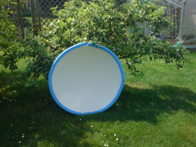
- 1 meter diameter parabolic dish from Ebay
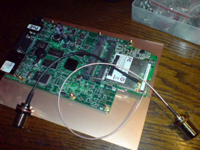
- Mikrotik RouterBoard 433
- WLM54SAG MiniPCI WLAN Interface
- Compex WLM54SAG
- 200mW (23 dBm)
- Atheros AR5414 Chipset
- 2 x U.FL Anschluss
- 802.11a/b/g
- R5H Mikrotik HighPower WLAN interface
- Custom Frequency License to transmit within the Amateur Radio bands
Cost estimate:
- dishes 60 Euro
- Router hardware 430 Euro
- several working hours
3 Software
Let me collect some links beforehand:
- http://wiki.oevsv.at/images/1/13/SetUpBB.pdf
- http://multimedia.oevsv.at/geiersberg2008/Projekt-Alan-DigitalerBackboneOE-VortragGeiersberg2008.ppt
4 Some considerations
4.1 Using preamps vs. PAs
In a discussion on Saturday 09.05.09 we found out that the receiver sensitivity of the WIFI cards we're using is far below all standards known for amateur radio devices. The specification says that the sensitivity is as low as -79 dB for 54 MBit/s connections (referring to a 22 MHz broad signal). As opposed to the transmission power and the prospected gains from the dish, the transmission path is not the side that will deserve our main attention: Enhancing the reception path will promise the highest gains.
Since it was our initial plan to place the router board directly into the focus of the dish, we decided against it, on grounds that we intend to use a highly selective preamplifier, just in the focus of the dish. Given that, the router board doesn't need to be in the focus any longer. Having less weight out there with half a meter of leverage, our dish will also gain more mechanical stability.
So it will be the task of Bernd, DJ6PA, to construct the ring exciters and the pair of preamplifiers - one for 13cm and one for 6 cm.
Given that we will be using preamplifiers anyway, we can live with the 0.5 dB loss of the H2000 cable that connects the preamp in the focus and the router board.
4.2 Mechanical stability vs. propagation angle
Our pair of dishes has a diameter of 1 meter. Sure, this will give us a gain of about 26 dB on the 6cm band and almost as much on the 13cm band. But such big dishes have a disadvantage: The propagation angle is extremely small. We calculate less tha 1 degree on 6 cm. The transmitted beam is thus very, very narrow. Since the dish is quite big nevertheless, it is very prone to vibrations caused by the wind.
With an estimated propagation angle of about 1 degree, in 30 kilometers distance the diameter of the beam will just be about 500 meters. So only slight vibrations of the mounts will cause the beam to be off the target. It will be vital for a stable link to mount the disk as mechanically stable as possible, and not just on one side, but on two sides.
As for the next milestone of the project, to set up a link over 30 kilometers, it might be more advisable to try a smaller dish at first. This is also an interesting insight given that we have established connections on 10 GHz between DB0MHB and stations in Regensburg using far less transmitting power and smaller dishes.
5 Installation
5.1 Burdens of the installation
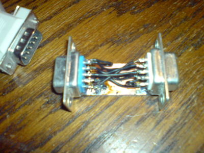
Before you can get access to the device, you need a Nullmodem. I just followed the cabling instuctions given here and it worked from the beginning.
 DTE 1                                        DTE 2
9pol 25pol (female)                          25pol 9pol (female)
5    7  ---GND---------------------GND-------  7   5

2    3  ---RxD--------. ,----------RxD-------  3   2
                       X
3    2  ---TxD--------' `----------TxD-------  2   3

7    4  ---RTS--------. ,----------RTS-------  4   7
                       X
8    5  ---CTS--------' `----------CTS-------  5   8

4   20  ---DTR--------. ,----------DTR------- 20   4
                       X
6    6  ---DSR--o-----' `-------o--DSR-------  6   6
                |               |
1    8  ---DCD--'               `--DCD-------  8   1
The speed is 115200 bit/s and the login credentials after a fresh installation are admin and no password.
5.2 Pick an operating frequency
- http://www.df3xz.de/Neue_Dateien/Bandpl%E4ne.pdf DF3XZ has a nice overview of bandplans.
I decided to pick the following frequencies for the link experiment:
- DB0MHB side
- 2392 MHz RX
- 5680 MHz TX
- DL8RDS side
- 5680 MHz RX
- 2392 MHz TX
5.3 Pick IPs
- DB0MHB: 44.128.12.10
- DL8RDS: 44.128.12.11
There's a test IP range we're using: 44.128.12.0/24
5.4 Ring Exciters
Antenna construction is probably most visible engineering effort in the entire project. We are constructing a weatherproof pair of concentrical ring exciters for the focus of the dishes. Here's some theory...
- http://www.w1ghz.org/antbook/chap11.pdf Paul Wade. The W1GHZ Online Microwave Antenna Book. Chapter 11. 2006. - Excellent explanation on possible causes for gain loss in a parabolic scenario.
- http://www.mydarc.de/dj6iy/ghz-antennen/ghz-ant.html
- http://www.antennex.com/w4rnl/
And some practical guidance:
- http://www.dd7mh.de/RingPraesentWeb/img0.html Ring Exciters from Hans DD7MH
And some print literature:
- S. Silver. Microwave Antenna and Design. McGraw-Hill, 1949. pp. 239 - 256.
- M.W. Dixon, G3PFR. Microwave Handbook. Volume 8. RSGB, 1992. p. 14.25.
- R. Sletten, KB1QV, C. Sletten, W1YLV. "An Efficient Feed for a 12" EME Dish". Proceedings of the Eighteenth Eastern VHF/UHF Conference. ARRL, 1992. pp. 67 - 70.
- D. Turrin, W2IMU. "Antenna Performance Measurements". QST, Nov 1974. pp. 35 - 41.
- EIA Standard RS.329.
- D. Turrin, W2IMU. "Parabolic Reflector Antennas and Feeds". The ARRL UHF/Microwave Experimenter's Manual. ARRL, 1990. p. 9 - 35.
- J.E. Pearson, KF4JU. "Modified Feed Antennas for Parabolic Dishes". Proceedings of Microwave Update '91. ARRL, 1991. pp 194 - 204.
- B. Larkin, W7PUA. "Dipole-Reflector Parabolic Dish Feeds for f/D of 0.2-0.4". QEX, Feb 1996. pp. 3 - 11.
The perimeter of the ring is 1 lambda (1 full wavelength). We calculate the wavelength with the formula
l = c / f where c = 300.000.000 m/s
Since it is easier to shorten stuff than to lengthen it, we're starting with slight overlengths:
- l = 12.6 cm for 2380 MHz
- l = 5.2 cm for 5680 MHz
Formula: u = 2 * pi * r where u is the perimeter (Umfang) and r is the radius
so r = u / (2 * pi)
accordingly:
- r = 20.05 mm for the 12.6 cm ring for 2380 MHz
- r = 8.28 mm for the 5.2 cm ring for 5680 MHz
The distance d to the reflector should be 1/8 * lambda, so
- d = 1.575 mm for the 12.6 cm ring for 2380 MHz
- d = 0.650 mm for the 5.2 cm ring for 5680 MHz
Hey, that's all pretty small....!
The exact length if the ring wires can be measured with a SWR meter / reflectometer that can determine the resonnance point of the antenna by comparing the fed and the reflected HF energy. You generally iterate over a frequency spectrum and measure some SWR values. Then you draw a graph. There should be a minimum at some point, but with overlengths the minimum should be below your target frequency. Now we can shorten the antenna until we have a perfect match at the operating frequency of our intention.
As the works are advancing, I will provide more information.
5.5 Cases
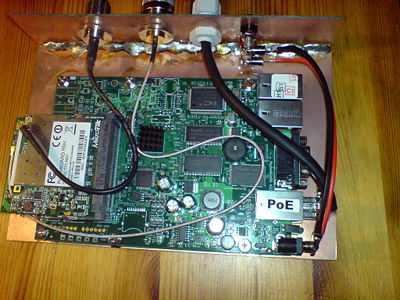
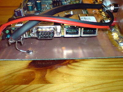
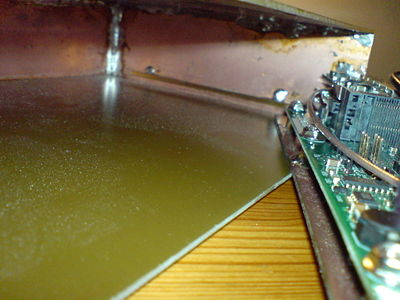
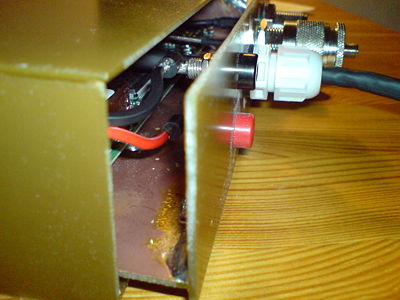
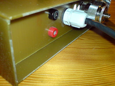
The cases are ready. I have built two cases for each Mikrotik board. The cases have consumed some thought, especially on how to make them weather-proof. I got inspired by the design of SSB's preamplifiers: The board carrier PCBs slide into the case from the bottom and are led by U profiles. The carrier board doesn't just slide in to shut the case but goes in a centimeter deeper to provide a drain ridge so the rain drops won't flow into the case. And finally, the current setup allows very easy sealing. Here are some photographs:
During the recent hot August summer days I noticed that the cases will heat up enormously when exposed to sunshine. In order to prevent overheating, I decided to apply some additional trick: I will attach mirror plates to the case to reflect the sunlight energy and reduce the absorbed heat.
5.6 Preamplifiers
On 5.680 GHz, a preamplifier of Michael Kuhne DB6NT will be used:
On 2.380 GHz, I am experimenting with another preamp (http://www.bmelectronics.de/) but we will see if that's a good solution.
The preamps will be mounted right on the feeds of the antennas.
5.7 Antenna Setup
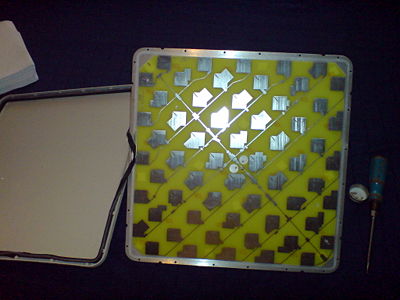
- 2010-02-28 Here's how a 5 GHz patch antenna looks like. Unfortunately the sample here is based on a regular PCB and not on Teflon or another substance. So there's some considerable loss already due to the carrier substance.
- 2010-03-13 The OMs from DL0AO (the contest station of the club in Amberg) agreed to build the antenna related stuff. So I am about to transport the dishes to Amberg.
5.8 Idea
This is just a little notepad for an idea: Since the Mikrotik boards as well as the RouterOS support the NSTREME mode where transmit and receove will be split across different cards, it would be possible to serve a link in duplex mode PLUS transvert it into the 10 GHz band. There, practically no bandwidth limitations apply...
The Atheros chipset covers the following base frequencies, among many others:
- 5000, 5005, 5010, 5015, 5020, 5025, 5030, 5035, 5040, 5045, 5050
- 5125, 5130, 5135, 5140, 5145, 5150, 5155, 5160, 5165, 5170, 5175
These frequencies could be transverted to frequencies in the frequency blocks
- 10000 - 10100
- 10250 - 10350
Which permits the establishment of really bold links...
- Sources: http://www.dd1us.de/Downloads/6cm-3cm.pdf
- http://www.qsl.net/kb9mwr/projects/wireless/modify.html
- http://mysite.verizon.net/michael_d_lewis/5.7GHz_Project.htm (K7MDL having similar ideas)
