Building an extremely small ARPS Tracker: Unterschied zwischen den Versionen
Aus DL8RDS Wiki
Dl8rds (Diskussion | Beiträge) (→Data) |
Dl8rds (Diskussion | Beiträge) (→Other data) |
||
| Zeile 68: | Zeile 68: | ||
[[Image:OT1SMT_Belegung.png|400px]] | [[Image:OT1SMT_Belegung.png|400px]] | ||
| + | |||
| + | And here's how to use the USB / Serial adapter from the Arduino projects: http://arduino.cc/en/Guide/ArduinoMini | ||
| + | |||
| + | I am using this adapter to program the SMT chip. | ||
== Project plan == | == Project plan == | ||
Version vom 5. November 2009, 04:47 Uhr
Inhaltsverzeichnis
1 Project goal
This project has the goal to assemble a lowest possibly imaginable power saving and absolute supercompact highly packed APRS traching transmitter.
2 Ingredients
At last, I got all my ingredients collected:
- EM-406A, a 20 Channel SiRF III GPS Receiver from USGlobalSat with Antenna
- Open Tracker SMT
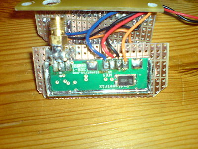
- Radiometrix HX1-144.800-3 300 mW transmitter
3 Data
3.1 Datasheets
- http://www.sparkfun.com/datasheets/GPS/EM-406A_User_Manual.PDF EM-406A User Manual
- http://www.datasheetarchive.com/pdf-datasheets/Datasheets-3/DSA-56110.pdf RadioMetrix Module Datasheet
3.2 References
- http://www.sparkfun.com/datasheets/GPS/NMEA%20Reference%20Manual1.pdf NMEA Reference
- http://wiki.argentdata.com/index.php/OpenTracker%2B
3.3 Other data
The tracker's inner values:
   * Voltage: DC 6.5 to 28V unregulated or 5V DC regulated
   * Current: 8 mA idle, 20 mA transmitting Max 200 mA @ 5 V available for GPS
   * Modes: 1200 bps AFSK (send and receive); 300 bps AFSK, PSK31 (send only)
   * Radio Connector: pin header
   * Serial Connector: pin header
   * Dimensions: 31mm x 18mm x 5mm
   * GPS interface: NMEA in/out
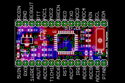
Pinout:
Pin  Name   Funktion
1    5VIN     Geregelter 5-Volt-Eingang
2    RxD      RS-232 Data in der (vom GPS oder Computer)
3    1Wire    Dallas 1-Draht-Bus für externe Sensoren
4    AOUT     Audio-Ausgang an Radio
5    ADC5     Analog-Eingang
6    T1CH1    Timer-Kanal
7    ADC6     Analog-Eingang
8    RST      Reset (active low)
9    ADC7     Analog-Eingang
10   IRQ-     Transmit-now, Profil wählen, oder Zähler
11   ADC8     Analog-Eingang
12   ADC9     Analog-Eingang
13   AIN      Audio-Eingang von Radio
14   ADC4     Analog-Eingang
15   ADC3     Analog-Eingang
16   TXD      RS-232 Data aus
17   rot      rot LED-Ausgang
18   grün     grün LED-Ausgang
19   ADC2     Analog-Eingang
20   ADC1     Analog-Eingang
21   PTT      Push-to-talk-Signal an Radio
22   REGOUT   Regulator-Ausgang - 5 Volt
23   GND      Ground
24   REGIN    Regulator-Eingang - 6,5 bis 28 Volt
- http://www.jaeger-edv.de/Shop/index.php?page=shop.getfile&file_id=40&product_id=25&option=com_virtuemart&Itemid=53 Config Tool for the OpenTracker SMT
The following picture is from ArgentData:
And here's how to use the USB / Serial adapter from the Arduino projects: http://arduino.cc/en/Guide/ArduinoMini
I am using this adapter to program the SMT chip.
4 Project plan
- Find a cabling arrangement that works
- Program the Opentracker SMT
- Rearrange all the three components on minimal space
- Build a suitable case
5 Tests
- Since I have my APRS relay station ready to go anyway, I just need the tracker to start tracking!

