A Microcontroller Operated SWR Meter: Unterschied zwischen den Versionen
Dl8rds (Diskussion | Beiträge) (→Control an ADC that is connected over I2C) |
Dl8rds (Diskussion | Beiträge) (→Controlling a PWM over I2C) |
||
| Zeile 418: | Zeile 418: | ||
} | } | ||
} | } | ||
| + | |||
| + | === Reading Input from an I2C ADC === | ||
| + | |||
| + | This might be helpful: | ||
| + | * http://www.arduino.cc/cgi-bin/yabb2/YaBB.pl?num=1231672744 | ||
| + | |||
| + | But... I have not yet been successful to wake up my BV4237 ADC. It simply doesn't want to work. | ||
== The Directional Coupler == | == The Directional Coupler == | ||
Version vom 25. Oktober 2009, 22:26 Uhr
Inhaltsverzeichnis
- 1 Project description
- 2 Other People's work
- 3 Shops where to buy the components
- 4 Project Plan
- 5 Progress
- 5.1 Purchase Stuff
- 5.2 First Steps on Arduino
- 5.2.1 Controlling digital Output
- 5.2.2 Controlling Serial Output
- 5.2.3 Evaluate an analog value through the ADC
- 5.2.4 Doing the same on the Arduino Nano
- 5.2.5 Controlling the Arduino over the serial connection
- 5.2.6 Controlling an LCD display
- 5.2.7 Writing stuff to the LCD display
- 5.2.8 Reading a value from the I2C port
- 5.2.9 Talking to the network
- 5.2.10 Controlling a PWM over I2C
- 5.2.11 Reading Input from an I2C ADC
- 5.3 The Directional Coupler
- 6 What's next?
1 Project description
This project is related to the SVXLink project. Since I intend to use T7F transceivers for this project, it is highly interesting to detect troublesome antenna and SWR conditions and to be able to shut off the transmitter. The only way to do that is to read out the SWR digitally. And this can be done using an Analog Digital Converter, either directly on a microcontroller board or over an I2C BUS.
BTW, I want to measure some more values:
- PA temperature
- Transmitter power consumption / input current
- Total system input current
And I want to switch some things, too:
- Be able to switch the transceiver OFF
But very basically this project can also be seen in an isolated perspective: I want to learn how to use a microcontroller and set up a project that's useful for other OMs as well. Notably interesting will be to use the Sparkfun Low Current readout boards and feed this voltage into the ADC that's contained on the Arduino board. so that I possibly don't even need the I2C BUS for this isolated scenario.
The LCD display is a ANAG Vision AV2020YFBF-SJ
2 Other People's work
- http://www.dk0fr.de/aktuell/DARC/SWR-Powermeter.pdf A similar project but on a different uC basis
- http://www.dj4uf.de/projekt/swr/swr.htm - cool idea for a simple directional coupler. I see that a Aircell cable is perfectly suited for this job.
- http://accrochages.drone.ws/en/node/125 - a voltage meter project based on the Arduino
- http://www.foxdelta.com/products/swr-hf.htm <- There you can buy pre-assembled kits, but that's not what I want.
- http://blog.makezine.com/archive/2008/05/hook_up_an_arduino_to_i2c.html
- http://www.neufeld.newton.ks.us/electronics/?p=241
- http://www.pr8-online.de/index.php?option=com_content&task=view&id=46&Itemid=33&lang=de Excellent introduction into LCD usage with the LCD screen I am using
3 Shops where to buy the components
- http://www.watterott.com (Germany)
- http://www.sparkfun.com/commerce/categories.php (USA)
- http://store.gravitech.us/ (USA)
- http://www.horter.de/ (Germany)
4 Project Plan
- Purchase stuff
- Get familiar with the Arduino board. See how to read out values and to control actuators.
- Build a directional coupler. Role model: http://www.dj4uf.de/projekt/swr/swr.htm
- Make sure the readouts of the forward voltages are within a reasonable range. identify peak voltages.
- Then take the BeagleBoard and be successful measuring voltages through a Analog Digital Converter (ADC).
- Then connect the coupler to the ADC and see if it's possible to measure the voltages.
- Then connect an LCD display to an Arduino board.
- Then successfully control the LCD display and devise a reasonable display readout
- Then read the I2C bus from the Arduino board
- Then calculate the SWR based on the readings from the I2C bus and send them to the LCD display
- Finally build a nice case
- Write an article and post it in some fancy electronics magazine :-)
5 Progress
5.1 Purchase Stuff
- 2009-09-04 The BeagleBoard has an I2C header in the expansion port. So it is just a wonderful idea to use it and read out some things. The only problem: It's operated with 1,8V. So I need a bidirectional voltage translator.
- I found one across the Atlantic at Ebay: Gravitech has such a thing for a decent price: http://gravitech.us/MicroResearch/I2C/I2C-TRN/I2C-TRN-Manual.pdf
- Another option would be to built it by myself using the PCA9306: http://focus.ti.com/docs/prod/folders/print/pca9306.html
- 2009-09-05 I decided to get the one from Gravitech.
- 2009-09-10 My ADC arrived. I'm still waiting to receive the voltage translator. And I have bought some books on Arduino programming. Still need to buy the Arduino board and an LCD display.
- ToDo: Go shopping
- 2x C 1nF
- 2x R 100 Ohm
- 2x diodes Schottkydiode
- http://www.sparkfun.com/commerce/product_info.php?products_id=8883
- 20cm Aircom cable. It has those practical canals in the dielectricum through which you can stick the sensor wires.
- The Arduino board and the LCD display
There are some guides on how to connect LCD dislays and Arduinos:
- http://blog.makezine.com/archive/2008/04/how_to_use_an_lcd_with_ar.html
- http://www.uchobby.com/index.php/2007/07/07/arduino-lcd-interfacing-part-1/
- http://www.ladyada.net/learn/arduino/lcd.html
5.2 First Steps on Arduino
My first steps on the Arduino platform are successful! Since I have been working on a Ubuntu Hardy platform, I noticed that I would not be able to compile my programs properly because there are some bugs here and there. Anyway, so I decided to upgrade to the most modern Ubuntu Jaunty distribution and now it works fine: I can start the Arduino development environment without problems. Trying out the first little program, the famous "Blink" program which blinks a LED, compiled perfectly. So I started over and plugged the LED into digital output pin 13 and GND and uploaded the code and there it went. The Arduino went blinking!!!
5.2.1 Controlling digital Output
int ledPin =  13;    // LED connected to digital pin 13

void setup()
{
  // initialize the digital pin as an output:
  pinMode(ledPin, OUTPUT);
}

void loop()
{
  digitalWrite(ledPin, HIGH);   // set the LED on
  delay(1000);                  // wait for a second
  digitalWrite(ledPin, LOW);    // set the LED off
  delay(1000);                  // wait for a second
}
5.2.2 Controlling Serial Output
My next experiment was to send stuff to the serial console back to the computer. Here I tried out some code from the book "Manuel Odendahl, Julian Finn & Alex Wenger. Arduino. Pysical Computing für Bastler, Designer & geeks. O'Reilly, 2009.", page 132 ff.
void setup()
{
  Serial.begin(9600);
}
void loop()
{
  Serial.println("Hallo");
  Serial.println("--------");
  delay(1000);
}
5.2.3 Evaluate an analog value through the ADC
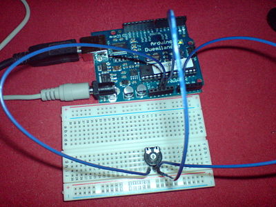
And after making a connection to /dev/ttyUSB0 with 9600 bit/s and handshake off, I was able to read the Hello by every second. So also the serial connection is damn simple. The next bit was even a bit harder: I want to read out the setting of a poti and send the value to the serial console. That's my first attempt to make a bridge from the real world into the digital world. Here's the setup:
The poti is a 1 kOhm.
And here's the code:
int potiPin = 0;
int potiVal = 0;

void setup() {
  Serial.begin(9600);
  int potiPin = 0;
}

void loop() {
  int zahl = 10;
  int potiVal = analogRead(potiPin);
  Serial.println("Poti-Wert:");
  Serial.println(potiVal);
  Serial.println("-------------");
  delay(1000);
}
And now when I take a screwdriver and twist around the poti, I am getting different values in my minicom!!!
Poti-Wert:
541
-------------
Poti-Wert:
561
-------------
Poti-Wert:
653
-------------
Poti-Wert:
804
-------------
Poti-Wert:
857
-------------
Poti-Wert:
1018
-------------
Poti-Wert:
1023
-------------
Poti-Wert:
1019
Most remarkable is that the values range from 0 to 1023. So that's just a perfect basis to do further calculations.
5.2.4 Doing the same on the Arduino Nano
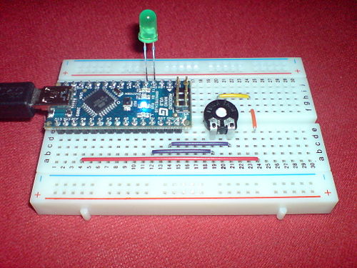
Yes, and because I like it small, there's the Arduino Nano. I did roughly the same again based on the Nano. In this case I connected the input from the Poti with the delay of the LED LOW. I can now regulate the blinking frequency. Here's a picture of the setup on my breadboard:
int potiPin = 0;
int potiVal = 0;
int ledPin = 2;

void setup() {
  int potiPin = 0;
  pinMode(ledPin, OUTPUT);
}

void loop() {
  int potiVal = analogRead(potiPin);
  digitalWrite(ledPin, HIGH);
  delay(100);
  digitalWrite(ledPin, LOW);
  delay(potiVal*2);
}
5.2.5 Controlling the Arduino over the serial connection
2009-09-19 The following program is there to demostrate how I can talk to the Arduino over the serial interface: After sending a character "B", the blinking goes off, and after sending a "A", it will start again:
int potiPin = 0;
int potiVal = 0;
int blink = 1;
int ledPin = 2;

void setup() {
  Serial.begin(9600);
  int potiPin = 0;
  pinMode(ledPin, OUTPUT);
}

void loop() {
  int potiVal = analogRead(potiPin);
  //Serial.println("Poti-Wert:");
  if (Serial.available() > 0) {
     char b = Serial.read();
     if (b == 65) {
        blink = 1;
     }
     if (b == 66) {
        blink = 0;
     }
  }

  if (blink == 1) {
     digitalWrite(ledPin, HIGH);
     delay(100);
     digitalWrite(ledPin,LOW);
     delay(potiVal*2);
  } else {
     digitalWrite(ledPin, LOW);
  }

  Serial.println(potiVal);
  //Serial.println("-------------");
  delay(10);
}
5.2.6 Controlling an LCD display
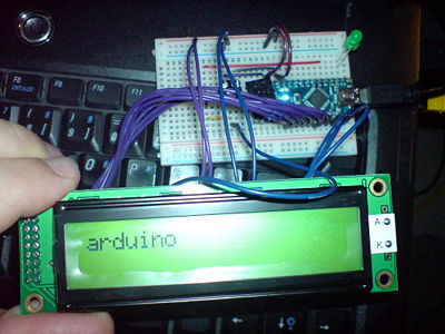
2009-09-25 After a short setback due to the misunderstood role of the poti that drives the contrast of the lcd panel, I tried it again and I was now successful in driving my LCD panel. I'd never have believed that it is so simple. If you don't see anything on your display but lit characters (nothing black), use a poti and feed a voltage between 0 and 5V into the contrast pin. I found out that in my case, the contrast will be there if I give it exactly 5V. So in my case no need for a poti. But keep in mind that LCDs are very sensitive to heat, so there might be a need to care for that once you mount it into a stable case.
Note that I didn't use a resistor to reduce the LCD backlight voltage from 5.0 to 4.2 V. The display can stand that at least for the test.
#include <LiquidCrystal.h>

// Wiring pattern: LiquidCrystal(rs,rw,enable,d0,d1,d2,d3,d4,d5,d6,d7)
LiquidCrystal lcd(12,11,10,9,8,7,6,5,4,3,2);

void setup() {
 lcd.print("arduino");
}

void loop() {}
5.2.7 Writing stuff to the LCD display
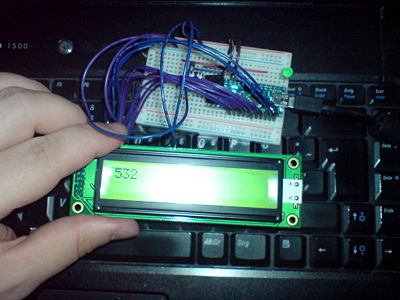
Yes, and this made me curious if I can also print the digitized value of the poti voltage to my LCD screen. I modified the program a little:
#include <LiquidCrystal.h>

int potiPin = 0;

LiquidCrystal lcd(12,11,10,9,8,7,6,5,4,3,2);

void setup() {
}

void loop() {
 lcd.clear();
 int potiVal = analogRead(potiPin);
 lcd.print(potiVal);
 delay(500);
}
Here's the result. The Arduino displays the poti setting (a value between 0 and 1023) on the LCD display.
This done, I'd consider myself proficient enough to start processing incoming voltages from a directional coupler. Let's no longer worry about the microcontroller. This is all under control and the program shall be written in a few moments. Now I must care for the hardware.
5.2.8 Reading a value from the I2C port
Just to make things complete, I'd like to paste my most recent experiment here. It's about controlling the I2C pins by reading from a temperature sensor and displaying it over the serial port.
My sensor is a LM75 type which has the default address 0x90 which boils down to an address setting of 0x48 (don't ask me why). But here's some funny code that actually works:
#include <Wire.h>
#define address 0x48

void setup()
{
  Wire.begin();
  Serial.begin(9600);
}

void loop()
{
  Wire.beginTransmission(address);
  Wire.send(0x00);
  Wire.requestFrom(address, 1);
  int temperature;
  if (Wire.available()) {
     temperature = Wire.receive();
  }
  Wire.endTransmission();
  Serial.println("-----------");
  Serial.println(temperature);
  delay(1000);
}
Please note that the communication pattern with the device is very much relative to the chip you're using. I found the following texts very helpful, from which I also took some crucial ideas:
- http://www.arduino.cc/cgi-bin/yabb2/YaBB.pl?num=1252352897/0 - I also have such a board
- http://www.nearfuturelaboratory.com/2007/01/11/arduino-and-twi/
- http://naneau.nl/2009/01/18/arduino-and-an-i2c-temperature-sensor/ - This is fantastic!!
- http://blog.makezine.com/archive/2008/05/hook_up_an_arduino_to_i2c.html That's good also!
Some notes on I2C addresse. The above given example requests the value from an address 0x48, whereas the datasheet and some other sources explain that the address of the temp sensor is 0x90. What's the difference? Let's convert these values to their binary form:
0x48 = 1001000
0x90 = 10010000
You see that the only difference is the last bit. Remember that the I2C bus has 7 bits for the addressing. The last bit defines the reading or writing direction. So the address is eventually just composed out of the first 7 bits. Omit the last bit and try again. Use a binary calculator for calculations such as these.
It is also interesting to know that temperature sensors of the same type use the same base addresses. I have been using the temp sensors LM75 and MPC9802 and they have the same base addresses. Notably the LM75 product from Horter&Kalb has the possibility to set the three last address bits through a jumper array. So you can operate a maximum of 8 temp sensors on one I2C bus.
Note that it would be possible to state the address alternatively in the binary form:
#define address B1001000
5.2.9 Talking to the network
Well, even this is most certainly no longer related to my SWR meter project, I just find that it's sooooo cool, so I will simply present some code here:
#include <Server.h>
#include <Ethernet.h>
#include <Client.h>
#include <Wire.h>
#define address 0x48
byte mac[] = {0xDE, 0xAD, 0xBE, 0xEF, 0xFE, 0xED};
byte ip[] = {192, 168, 178, 190};
byte gateway[] ={192,168,178,1};
byte subnet[] = {255,255,255,0};
Server server = Server(80);
void setup()
{
Wire.begin();
Serial.begin(9600);
Ethernet.begin(mac, ip, gateway, subnet);
server.begin();
}
void loop()
{
Client client = server.available();
if (client) {
Wire.beginTransmission(address);
Wire.send(0x00);
Wire.requestFrom(address, 1);
int temperature;
if (Wire.available()) {
temperature = Wire.receive();
}
Wire.endTransmission();
server.print("HTTP/1.0 200 OK\r\nServer: arduino\r\n");
server.print("Content Type: text/html\r\n\r\n");
server.print("Zimmertemperatur </head>\r\n");
server.print("<body>Zimmertemperatur:<p>\r\n");
server.print(temperature-4);
server.print("<p>Uptime:");
server.print(millis());
server.print("ms.");
delay(10);
client.stop();
Serial.println("-----------");
Serial.println(temperature);
}
}
It will show the room temperature of my lab. I used the above mentioned LM75 sensor from Horter and the Ethernet shield with the WIZnet Ethernet module that you can purchase from Watterott. Also have a look there:
http://www.mats-vanselow.de/2009/01/30/arduino-ins-netz-bringen/
Given that my controller grabs the temperature from the source via I2C, it would be no problem to connect several sensors over this bus. It would be possible to read out a huge number of data sources...
5.2.10 Controlling a PWM over I2C
Pulse Width Modulation is a way to control the production of voltages. The hardware that is being used here is a BV4237:
The below given code sample is based on the code presented by the BB user wilkosoft:
#include <Wire.h>

#define dac 0x31

void sw16set(byte val) {
  Wire.beginTransmission(dac);  // join I2C, talk to BV4206 by id
  Wire.send(0x16);   //tell it what pin you want
  Wire.send(val);  //the state of the pin, from 0-8 (PWM controls the levels)
  Wire.endTransmission();      // leave I2C bus
  delay(100) ;
}

void setup()
{
  Wire.begin();
  Serial.begin(9600);
}

void loop()
{
  for (byte i=0; i<9; i++) {
    sw16set(i);
  }
}
5.2.11 Reading Input from an I2C ADC
This might be helpful:
But... I have not yet been successful to wake up my BV4237 ADC. It simply doesn't want to work.
5.3 The Directional Coupler
I'm just about organizing the hardware.
6 What's next?
- Come back and see in a few weeks / months...


