Web based ATV Relay Control
Inhaltsverzeichnis
1 Scope
Our ATV relay DB0MHB is a microcontroller based system that can be controlled through DTMF tones, but is still lacking HAMNET support even though we have HAMNET connectivity at our location.
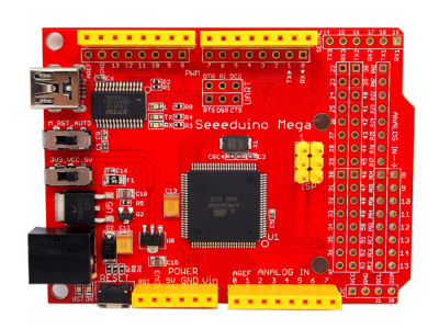
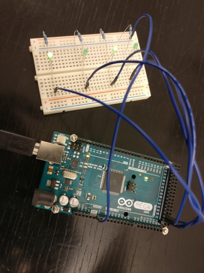
In order to control it through a web page, we decided to upgrade it with pinouts from the DTMF panel. These pinouts will be translated in an ARDUINO Mega 1280 which has a sufficient number of GPIOs, and the Arduino is supposed to provide a serial interface to the relay.
The serial interface will be controlled again through a Raspberry Pi that does all the rest.
The most remarkable feature is a shell like interface that allows to invoke commands and provides a history function.
We decided to implement the relay logic in the Raspberry and use the Arduino only as a GPIO swithing interface module, since relay functions are subject to change, and these changes are easier to modify than controller code.
The Arduino board also has a LM75 I2C temperature sensor mounted, so it seemed reasonable to support a query function.
2 Useful Links
- http://www.horter.de/i2c/i2c-beispiele/arduino_1.html
- https://github.com/basilfx/Arduino-CommandLine
- https://github.com/fakufaku/CmdArduino
- http://vitech-blog.de/raspberry-pi-temperaturmessung-mit-dem-lm75/
3 Files
4 Libraries
In my first attempt I tried to scale the T (=Taste) commandset to T1..TD including * and #, but I found out that it failed to support more than T1 - T6 commands, T7 was no longer reachable, for whatever reason. Deeper diagnostics into the library code seemed not efficient, so I decided to try another library.
The first library I used was this: https://github.com/basilfx/Arduino-CommandLine
The second library I tried gave me way better results: https://github.com/fakufaku/CmdArduino
Adding commands was easy.
5 Connectivity
We have a 37 pin cable coming down from the relay controller into my Arduino Mega 1280. The 1280 has a sufficient number of GPIOs, so that's fine. Unfortunately we have a small twister, so two cables are not wired correctly. No matter, we can compensate that in the code...
The DTMF keyboard that needs to be emulated, is controlled through four lines:
- Bit1
- Bit2
- Bit4
- Bit8
Accordingly 16 keys can be addressed, while the last key (D) equals 0000 and is taken as a zero state (setback).
We have the following line matrix:
- Serial Pin 1 <-> 12V geht bei TX auf 0V
- Serial Pin 2 <-> 12V Status Grundbild
- Serial Pin 3 <-> 12V Status Umsetzbetrieb
- Serial Pin 4 <-> 12V Status Panoramakamera
- Serial Pin 5 <-> 12V Status S-Meter Azimut Anzeige 7Segment Anzeigen
- Serial Pin 6 <-> 12V Status DB0KN
- Serial Pin 7 <-> 12V Status Betriebsanleitung
- Serial Pin 8 <-> 12V Status Eckkamera
- Serial Pin 9 <-> 12V Status Innenkamera
- Serial Pin 10 <-> 12V Status RX Zusatz (Frei)
- Serial Pin 11 <-> 12V Status 2k2 Frei
- Serial Pin 12 <-> N.C. Eigentlich: 12V Rückkanal DTMF Taste 1
- Serial Pin 13 <-> N.C. Eigentlich: 12V Rückkanal DTMF Taste 2
- Serial Pin 14 <-> N.C. Eigentlich: 12V Rückkanal DTMF Taste 3
- Serial Pin 15 <-> N.C. Eigentlich: 12V Rückkanal DTMF Taste 4
- Serial Pin 16 <-> N.C. Eigentlich: 12V Rückkanal DTMF Taste 5
- Serial Pin 17 <-> N.C. Eigentlich: 12V Rückkanal DTMF Taste 6
- Serial Pin 18 <-> N.C. Eigentlich: 12V Rückkanal DTMF Taste 7
- Serial Pin 19 <-> N.C. Eigentlich: 12V Rückkanal DTMF Taste 8
- Serial Pin 20 <-> N.C. Eigentlich: 12V Rückkanal DTMF Taste 9
- Serial Pin 21 <-> N.C. Eigentlich: 12V Rückkanal DTMF Taste 0
- Serial Pin 22 <-> N.C. Eigentlich: 12V Rückkanal DTMF Taste A
- Serial Pin 23 <-> N.C. Eigentlich: 12V Rückkanal DTMF Taste B
- Serial Pin 24 <-> N.C. Eigentlich: 12V Rückkanal DTMF Taste C
- Serial Pin 25 <-> N.C. Eigentlich: 12V Rückkanal DTMF Taste #
- Serial Pin 26 <-> N.C. Eigentlich: 12V Rückkanal DTMF Taste *
- Serial Pin 27 <-> N.C.
- Serial Pin 28 <-> N.C.
- Serial Pin 29 <-> N.C.
- Serial Pin 30 <-> N.C.
- Serial Pin 31 <-> N.C.
- Serial Pin 32 <-> N.C.
- Serial Pin 33 <-> N.C.
- Serial Pin 34 <-> Bit2 <-> GPIO 50
- Serial Pin 35 <-> Bit1 <-> GPIO 51
- Serial Pin 36 <-> Bit4 <-> GPIO 52
- Serial Pin 37 <-> Bit8 <-> GPIO 53
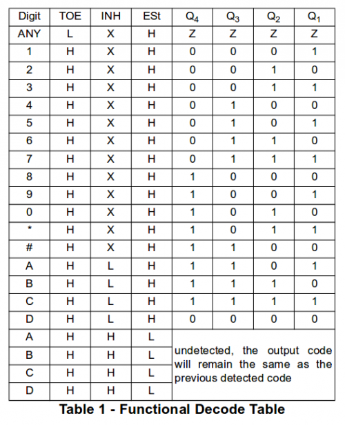
And the keyboard uses the following binary codings, with the binary string as (Bit8 - Bit4 - Bit2 - Bit1)
The following matrix is taken from the datasheet of the DTMF receiver IC MT8870D:
- Key 1 <-> 0001
- Key 2 <-> 0010
- Key 3 <-> 0011
- Key 4 <-> 0100
- Key 5 <-> 0101
- Key 6 <-> 0110
- Key 7 <-> 0111
- Key 8 <-> 1000
- Key 9 <-> 1001
- Key 0 <-> 1010
- Key A <-> 1101
- Key B <-> 1110
- Key C <-> 1111
- Key D <-> 0000 (Setback code! Not used!)
- Key * <-> 1011
- Key # <-> 1100
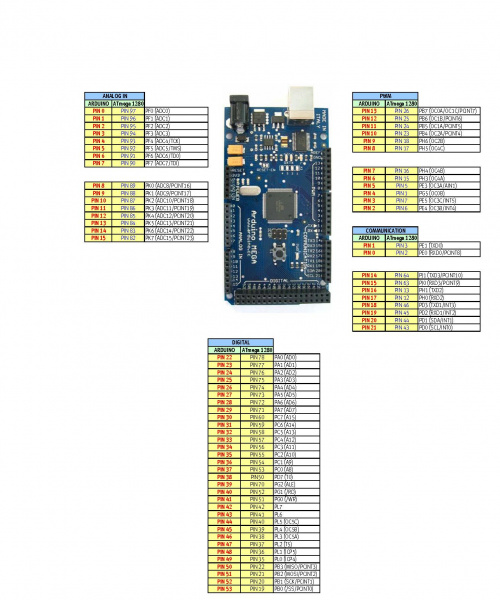
Here are some important notes. We have been using a Seeeduino Mega 1280 as a productive controller and a classic Arduino Mega 2560 as a dev system. We found out that when setting ports directly, the code is not portable, because the Seeeduino uses totally different wiring schemes referring to CPU ports. Here are the differences:
6 Arduino Code
I a first setup we implemented the connection between the Arduino / Seeeduino and the relay with optocouplers since the relay expected 12V and the Arduino only provided 5V, and we also found that the voltage was breaking down due to a low impedance on the relay side. We found that the relay was not landing in the basic picture as expected but in relaying mode. Clearly a mistake.
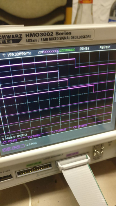
After some diagnosis with a logic analyzer we understood that optocouplers have a retarded output despite a decently syncronous input.
After this result we implemented a transistor based logic and now it works like a charm. Insight: Do not use optocouplers if you have a timing sensitive application!
6.1 Final Arduino Code
Here are good ressources:
- https://www.arduino.cc/en/Reference/PortManipulation
- http://www.netzmafia.de/skripten/hardware/Arduino/Programmierung/portmanipulation.html
And accordingly the code looks like this:
// Anmerkung: Dieses Programm funktioniert NUR auf dem Seeeduino Mega 1280, der am DB0MHB verbaut ist.
// Grund: Die Ausgaenge sind auf der PJ-Bank angeschlossen, die es so auf anderen Controllern nicht gibt.

#include <Wire.h>
#include <Cmd.h>

const int signaldauer = 200;

const int ser1 = 22;
const int ser2 = 23;
const int ser3 = 24;
const int ser4 = 25;
const int ser5 = 26;
const int ser6 = 27;
const int ser7 = 28;
const int ser8 = 29;
const int ser9 = 30;
const int ser10 = 31;
const int ser11 = 32;

#define SensorAdresse 0x48 // Basisadresse für ersten Temperatursensor
// Registerparameter fuer get_LM75_temperature
#define TEMP 0  // Temperaturregister anwählen

// LM75 Configuration Register Registeradresse: 1
// Bit 0: Stromsparmodus, bei 1 geht Temperatursensor in den Stromsparmodus (keine Messung, aber aktive Steuerung) Ausgang wird auch abgeschaltet
//                        bei 0 geht Temperatursensor aus dem Stromsparmodus (Messung) Ausgang wird wieder freigegeben
// Bit 1: Interrupt Modus, bei 1 schaltet der Ausgang sowohl bei oberen als auch unteren Schwellwert ein, wird zurückgesetzt durch Auslesen des Registers
//                         bei 0 schaltet der Ausgang bei oberen Schaltpunkt ein und bei unteren aus (default 80°C / 75°C)
// Bit 2: OS-Pin bei 1 wird das Verhalten des Ausgangs invertiert, Ausgang ist eingeschalten innerhalb der Schwellwerte
//               bei 0 Ausgang schaltet bei Überschreiten der eingestellten Schwellwerte
// Bit 3 und 4: Wert 0-3, besagt wieviele Messzyklen abgewartet wird, bis Ausgang aktiv/inaktiv wird, wenn die Bedingung erfüllt ist (verhindert Flattern des Ausgangs)
// Bit 5-7 müssen 0 sein
// Byte: 7 6 5 4 3 2 1 0

// LM75 Temperatur auslesen. Device = 0-7, regx = TEMP, OBEN, UNTEN (Registerauswahl)
double get_LM75_temperature(int device, int regx)
{
  int8_t msb;
  int8_t lsb;
  int8_t msb1;
  Wire.beginTransmission(SensorAdresse + device);
  Wire.write(regx);
  Wire.endTransmission();
  Wire.beginTransmission(SensorAdresse + device);
  Wire.requestFrom(SensorAdresse + device, 2);
  if (Wire.available()) {
     msb1 = Wire.read();
     msb = msb1 << 1; // Vorzeichenbit entfernen, verbliebener Wert ist nun doppelt so groß
     lsb = Wire.read();
  }
  // höchstes bit von lsb sagt aus, ob 0,5 Grad dazu addiert werden sollen
  lsb = (lsb & 0x80 ) >> 7; // nun ist lsb = 0 oder 1
  Wire.endTransmission();
  if (msb1 < 0x80) { // Positiver Wert?
    return double(msb + lsb)/2; // positiver Wert
  }
  else {
    return double(msb + lsb)/2 - 128; // negativer Wert
  }
}


void setup()
{
  Wire.begin();

  // Bank J, 2, 3, 4, 5 als Input
  DDRJ = B00111100;

  pinMode(ser1, INPUT);
  pinMode(ser2, INPUT);
  pinMode(ser3, INPUT);
  pinMode(ser4, INPUT);
  pinMode(ser5, INPUT);
  pinMode(ser6, INPUT);
  pinMode(ser7, INPUT);
  pinMode(ser8, INPUT);
  pinMode(ser9, INPUT);
  pinMode(ser10, INPUT);
  pinMode(ser10, INPUT);

  // init the command line and set it for a speed of 57600
  cmdInit(115200);

  // add the commands to the command table. These functions must
  // already exist in the sketch. See the functions below.
  // The functions need to have the format:
  //
  // void func_name(int arg_cnt, char **args)
  //
  // arg_cnt is the number of arguments typed into the command line
  // args is a list of argument strings that were typed into the command line
  cmdAdd("h",     handleHelp);
  cmdAdd("t",     handleTemp);
  cmdAdd("s",     handleState);
  cmdAdd("1",     handleT1);
  cmdAdd("2",     handleT2);
  cmdAdd("3",     handleT3);
  cmdAdd("4",     handleT4);
  cmdAdd("5",     handleT5);
  cmdAdd("6",     handleT6);
  cmdAdd("7",     handleT7);
  cmdAdd("8",     handleT8);
  cmdAdd("9",     handleT9);
  cmdAdd("0",     handleT0);
  cmdAdd("a",     handleTA);
  cmdAdd("b",     handleTB);
  cmdAdd("c",     handleTC);
  cmdAdd("*",     handleTStern);
  cmdAdd("#",     handleTHash);

  cmdAdd("t1",    handleT1);
  cmdAdd("t2",    handleT2);
  cmdAdd("t3",    handleT3);
  cmdAdd("t4",    handleT4);
  cmdAdd("t5",    handleT5);
  cmdAdd("t6",    handleT6);
  cmdAdd("t7",    handleT7);
  cmdAdd("t8",    handleT8);
  cmdAdd("t9",    handleT9);
  cmdAdd("t0",    handleT0);
  cmdAdd("ta",    handleTA);
  cmdAdd("tb",    handleTB);
  cmdAdd("tc",    handleTC);
  cmdAdd("t*",    handleTStern);
  cmdAdd("t#",    handleTHash);

  cmdAdd("h1",    handleH1);
  cmdAdd("h2",    handleH2);
  cmdAdd("h3",    handleH3);
  cmdAdd("h4",    handleH4);

  cmdAdd("l",     handleL);

}

void loop()
{
  cmdPoll();
}


void handleTemp(int arg_cnt, char **args)
{
  Serial.println("OK");
  char dataString[7]; // gelesene Temperatur als String aufbereitet: (-xx)x.x
  double temp; // gelesene Temperatur als double

  temp = get_LM75_temperature(0, TEMP); //(Device)Wert vom 1. Temperatursensor lesen (0-7, je nach Jumperstellung am Board, 2. Parameter wie oben definiert)
  dtostrf(temp, 4, 1, dataString); //dtostrf(floatVar, minStringWidthIncDecimalPoint, numVarsAfterDecimal, charBuf); (standard avr-libc function)

  Serial.print("Temp: ");
  Serial.println(dataString);
}

void handleState(int arg_cnt, char **args)
{
  Serial.println("OK");

  int s1 = digitalRead(ser1);
  int s2 = digitalRead(ser2);
  int s3 = digitalRead(ser3);
  int s4 = digitalRead(ser4);
  int s5 = digitalRead(ser5);
  int s6 = digitalRead(ser6);
  int s7 = digitalRead(ser7);
  int s8 = digitalRead(ser8);
  int s9 = digitalRead(ser9);
  int s10 = digitalRead(ser10);
  int s11 = digitalRead(ser11);

  if (s1 == HIGH) {
    Serial.println("S1 HIGH  - Relais inaktiv");
  } else {
    Serial.println("S1 LOW   - Relais aktiv");
  }

  if (s2 == HIGH) {
    Serial.println("S2 HIGH  - Grundbild aktiv");
  } else {
    Serial.println("S2 LOW   - Grundbild inaktiv");
  }

  if (s3 == HIGH) {
    Serial.println("S3 HIGH  - Umsetzbetrieb aktiv");
  } else {
    Serial.println("S3 LOW   - Umsetzbetrieb inaktiv");
  }

  if (s4 == HIGH) {
    Serial.println("S4 HIGH  - Panoramakamera aktiv");
  } else {
    Serial.println("S4 LOW   - Panoramakamera inaktiv");
  }

  if (s5 == HIGH) {
    Serial.println("S5 HIGH  - S-Meter aktiv");
  } else {
    Serial.println("S5 LOW   - S-Meter inaktiv");
  }

  if (s6 == HIGH) {
    Serial.println("S6 HIGH  - DB0KN aktiv");
  } else {
    Serial.println("S6 LOW   - DB0KN inaktiv");
  }

  if (s7 == HIGH) {
    Serial.println("S7 HIGH  - Betriebsanleitung aktiv");
  } else {
    Serial.println("S7 LOW   - Betriebsanleitung inaktiv");
  }

  if (s8 == HIGH) {
    Serial.println("S8 HIGH  - Eckkamera aktiv");
  } else {
    Serial.println("S8 LOW   - Eckkamera inaktiv");
  }

  if (s9 == HIGH) {
    Serial.println("S9 HIGH  - Innenkamera aktiv");
  } else {
    Serial.println("S9 LOW   - Innenkamera inaktiv");
  }

  if (s10 == HIGH) {
    Serial.println("S10 HIGH - RX Zusatz aktiv");
  } else {
    Serial.println("S10 LOW  - RX Zusatz inaktiv");
  }

  if (s11 == HIGH) {
    Serial.println("S11 HIGH - RX Zusatz 2 aktiv");
  } else {
    Serial.println("S11 LOW  - RX Zusatz 2 inaktiv");
  }

}

void handleHelp(int arg_cnt, char **args)
{
  Serial.println("OK");

  Serial.println("Kommandos: 'h (Hilfe)', 't (Temperatur)', 's (Status)', '1234567890abc*#' (DTMF-Tasten), h(1234) (Einzelpins dauerhaft HI), l (Alle LOW).");
}

void handleT1(int arg_cnt, char **args)
{
  Serial.println("OK");

  PORTJ |= B000100;

  delay(signaldauer);

  PORTJ = B00000000;

  Serial.println("Sent: 0001 (1)");
}

void handleT2(int arg_cnt, char **args)
{
  Serial.println("OK");

  PORTJ |= B001000;

  delay(signaldauer);

  PORTJ = B00000000;

  Serial.println("Sent: 0010 (2)");
}

void handleT3(int arg_cnt, char **args)
{
  Serial.println("OK");

  PORTJ |= B001100;

  delay(signaldauer);

  PORTJ = B00000000;

  Serial.println("Sent: 0011 (3)");
}

void handleT4(int arg_cnt, char **args)
{
  Serial.println("OK");

  PORTJ |= B010000;

  delay(signaldauer);

  PORTJ = B00000000;

  Serial.println("Sent: 0100 (4)");
}

void handleT5(int arg_cnt, char **args)
{
  Serial.println("OK");

  PORTJ |= B010100;

  delay(signaldauer);

  PORTJ = B00000000;

  Serial.println("Sent: 0101 (5)");
}

void handleT6(int arg_cnt, char **args)
{
  Serial.println("OK");

  PORTJ |= B011000;

  delay(signaldauer);

  PORTJ = B00000000;

  Serial.println("Sent: 0110 (6)");
}

void handleT7(int arg_cnt, char **args)
{
  Serial.println("OK");

  PORTJ |= B011100;

  delay(signaldauer);

  PORTJ = B00000000;

  Serial.println("Sent: 0111 (7)");
}

void handleT8(int arg_cnt, char **args)
{
  Serial.println("OK");

  PORTJ |= B100000;

  delay(signaldauer);

  PORTJ = B00000000;

  Serial.println("Sent: 1000 (8)");
}

void handleT9(int arg_cnt, char **args)
{
  Serial.println("OK");

  PORTJ |= B100100;

  delay(signaldauer);

  PORTJ = B00000000;

  Serial.println("Sent: 1001 (9)");
}

void handleT0(int arg_cnt, char **args)
{
  Serial.println("OK");

  PORTJ |= B101000;

  delay(signaldauer);

  PORTJ = B00000000;

  Serial.println("Sent: 1010 (0)");
}

void handleTA(int arg_cnt, char **args)
{
  Serial.println("OK");

  PORTJ |= B110100;

  delay(signaldauer);

  PORTJ = B00000000;

  Serial.println("Sent: 1101 (A)");
}

void handleTB(int arg_cnt, char **args)
{
  Serial.println("OK");

  PORTJ |= B111000;

  delay(signaldauer);

  PORTJ = B00000000;

  Serial.println("Sent: 1110 (B)");
}

void handleTC(int arg_cnt, char **args)
{
  Serial.println("OK");

  PORTJ |= B111100;

  delay(signaldauer);

  PORTJ = B00000000;

  Serial.println("Sent: 1111 (C)");
}

void handleTStern(int arg_cnt, char **args)
{
  Serial.println("OK");

  PORTJ |= B101100;

  delay(signaldauer);

  PORTJ = B00000000;

  Serial.println("Sent: 1011 (*)");
}

void handleTHash(int arg_cnt, char **args)
{
  Serial.println("OK");

  PORTJ |= B110000;

  delay(signaldauer);

  PORTJ = B00000000;

  Serial.println("Sent: 1100 (#)");
}

void handleH1(int arg_cnt, char **args)
{
  Serial.println("OK");

  PORTJ |= B000100;

  Serial.println("Sent: 0001 (h1)");
}

void handleH2(int arg_cnt, char **args)
{
  Serial.println("OK");

  PORTJ |= B001000;

  Serial.println("Sent: 0010 (h2)");
}

void handleH3(int arg_cnt, char **args)
{
  Serial.println("OK");

  PORTJ |= B010000;

  Serial.println("Sent: 0100 (h3)");
}

void handleH4(int arg_cnt, char **args)
{
  Serial.println("OK");

  PORTJ |= B100000;

  Serial.println("Sent: 1000 (h4)");
}

void handleL(int arg_cnt, char **args)
{
  Serial.println("OK");

  PORTJ = B00000000;

  Serial.println("Sent: 0000 (l)");
}
6.2 Serial Interface Usage Example
Serial communication through the serial interface looks like this:
Welcome to minicom 2.6.1

OPTIONS: I18n
Compiled on Apr 24 2017, 22:21:17.
Port /dev/ttyUSB0

Press CTRL-A Z for help on special keys

h
OK
Kommandos: 'h (Hilfe)', 't (Temperatur)', 's (Status)', '1234567890abc*#' (DTMF-Tasten), h(1234) (Einzelpins dauerhaft HI), l (Alle LOW).

*************** CMD *******************
CMD >> t
OK
Temp:  0.5

*************** CMD *******************
CMD >> s
OK
S1 HIGH  - Relais inaktiv
S2 LOW   - Grundbild inaktiv
S3 LOW   - Umsetzbetrieb inaktiv
S4 LOW   - Panoramakamera inaktiv
S5 LOW   - S-Meter inaktiv
S6 LOW   - DB0KN inaktiv
S7 LOW   - Betriebsanleitung inaktiv
S8 LOW   - Eckkamera inaktiv
S9 LOW   - Innenkamera inaktiv
S10 LOW  - RX Zusatz inaktiv
S11 LOW  - RX Zusatz 2 inaktiv

*************** CMD *******************
CMD >> *
OK
Sent: 1011 (*)

*************** CMD *******************
CMD >> s
OK
S1 LOW   - Relais aktiv
S2 HIGH  - Grundbild aktiv
S3 LOW   - Umsetzbetrieb inaktiv
S4 LOW   - Panoramakamera inaktiv
S5 LOW   - S-Meter inaktiv
S6 LOW   - DB0KN inaktiv
S7 LOW   - Betriebsanleitung inaktiv
S8 LOW   - Eckkamera inaktiv
S9 LOW   - Innenkamera inaktiv
S10 LOW  - RX Zusatz inaktiv
S11 LOW  - RX Zusatz 2 inaktiv

*************** CMD *******************
CMD >>
7 Raspberry Pi Code
7.1 Commandline tool for the serial port
This code gives me the same behaviour as a minicom session. It also allows to chain invocations on the commandline:
#!/usr/bin/env python

# (c) 2018 Markus Heller, M.A. DL8RDS, relix GmbH

serialport="/dev/ttyUSB0"
portspeed = 115200

import time
import serial
import sys
import cgi
import json
import os
from getpass import getpass
#from time import sleep

if not os.access(serialport, os.W_OK):
    print "Serial port not accessable >" + serialport
    sys.exit(1)

# configure the serial connections (the parameters differs on the device you are connecting to)
ser = serial.Serial(
    port=serialport,
    baudrate=portspeed,
    bytesize=serial.EIGHTBITS,
    parity=serial.PARITY_NONE,
    stopbits=serial.STOPBITS_ONE
)

ser.isOpen()

def interaction(input):
    ser.write(input + '\r')
    ser.flush()
    time.sleep(1)
    out = ''
    while ser.inWaiting() > 0:
        out += ser.read(1)
    return out[len(input)+2:]

def singlecommand(input):
    test = 0
    while 1 :
        test += 1
        out=interaction("")
        if out.endswith(">> "):
            break
    out = interaction(input)
    if not "OK" in out:
        print "Comms FAIL"
        sys.exit(1)
    return out

def cgicommand():
    print("Content-Type: text/html\n\n")
    arguments = cgi.FieldStorage()
    command = arguments.getvalue('command')
    if command:
        interaction(command)

def loop():
    print 'Setting up Communications'

    test = 0
    while 1 :
        test += 1
        print "Sending empty trigger"
        out=interaction("")
        if out.endswith(">> "):
            print "Comms Init successful"
            break
        if test > 2:
            print "Comms FAIL"
            sys.exit(1)

    print 'Insert "exit" to leave the application.'
    print 'Enter your commands below.'

    print "CMD",

    while 1 :
        # get keyboard input
        input = raw_input(">> ")

        if input in ['exit', 'e', 'q']:
            ser.close()
            exit()
        else:
            out = interaction(input)[:-4]
            print out,

if __name__ == "__main__":
    if len(sys.argv) == 1:
        #cgicommand()
        loop()
    else:
        for arg in sys.argv[1:]:
           print singlecommand(arg)
It allows to activate the ATV relay:
# activate and switch to input channel 8:
./atvctl.py t* t8
7.2 CGI script to control the commandline tool
But it can also be invocated by a CGI script. Here is what we're using:
#!/usr/bin/python

import os
import atvctl
import cgi
#import cgitb; cgitb.enable()  # for troubleshooting

form = cgi.FieldStorage()

string = form.getvalue('q')

print "Content-type: text/html\r\n\r\n";

# Diagnostics:
#for param in os.environ.keys():
#   print "<b>%20s</b>: %s<\br>" % (param, os.environ[param])

atvctl.singlecommand(string)

print "Erfolg : " + string + "\n"
This script is called from our internal control page via a XMLHttpRequest function.
7.3 Control Element
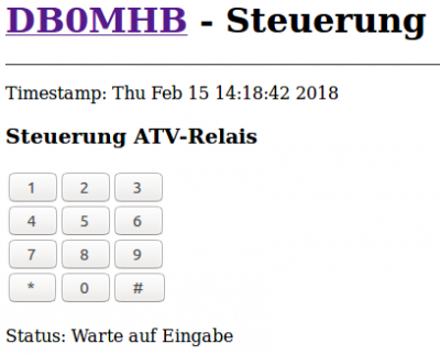
The control element (the DTMF keyboard) is generated like this:
<table>
<tr>
<td><input type="button" width="60" class="button" value="  1   " onClick="steuertaste('/cgi-bin/steuerung/atv-command.py?q=1','atv')"/></td>
<td><input type="button" width="60" class="button" value="  2   " onClick="steuertaste('/cgi-bin/steuerung/atv-command.py?q=2','atv')"/></td>
<td><input type="button" width="60" class="button" value="  3   " onClick="steuertaste('/cgi-bin/steuerung/atv-command.py?q=3','atv')"/></td>
</tr>
<tr>
<td><input type="button" width="60" class="button" value="  4   " onClick="steuertaste('/cgi-bin/steuerung/atv-command.py?q=4','atv')"/></td>
<td><input type="button" width="60" class="button" value="  5   " onClick="steuertaste('/cgi-bin/steuerung/atv-command.py?q=5','atv')"/></td>
<td><input type="button" width="60" class="button" value="  6   " onClick="steuertaste('/cgi-bin/steuerung/atv-command.py?q=6','atv')"/></td>
</tr>
<tr>
<td><input type="button" width="60" class="button" value="  7   " onClick="steuertaste('/cgi-bin/steuerung/atv-command.py?q=7','atv')"/></td>
<td><input type="button" width="60" class="button" value="  8   " onClick="steuertaste('/cgi-bin/steuerung/atv-command.py?q=8','atv')"/></td>
<td><input type="button" width="60" class="button" value="  9   " onClick="steuertaste('/cgi-bin/steuerung/atv-command.py?q=9','atv')"/></td>
</tr>
<tr>
<td><input type="button" width="60" class="button" value="  *   " onClick="steuertaste('/cgi-bin/steuerung/atv-command.py?q=*','atv')"/></td>
<td><input type="button" width="60" class="button" value="  0   " onClick="steuertaste('/cgi-bin/steuerung/atv-command.py?q=0','atv')"/></td>
<td><input type="button" width="60" class="button" value="  #   " onClick="steuertaste('/cgi-bin/steuerung/atv-command.py?q=#','atv')"/></td>
</tr>
</table>
As you can see, a clock triggers a function call to the JavaScript function "steuertaste", which implements the XMLHttpRequest object invocation, pointing to the CGI script given above.
Here is what it looks like:
