APRS with the Raspberry Pi and the TNC-X board
Inhaltsverzeichnis
1 Motivation
After my first series of experiments with APRS and Arduino, but also with APRS and OpenWRT I am now trying out something else:
Using a Raspberry Pi as a APRS gateway. In this case I intend to do it bidirectional.
2 Results
2.1 The deployed units
- Unit 1: http://aprs.fi/info/a/DB0RGB-1
- Unit 3: http://aprs.fi/info/a/DB0MHB-1
2.2 Reach distance of the stations
- DB0RGB: http://aprs.fi/#!mt=roadmap&z=11&v=gated&call=a%2FDB0RGB-1&timerange=3600&tail=3600
- DB0MHB: http://aprs.fi/#!mt=roadmap&z=11&v=gated&call=a%2FDB0MHB-1&timerange=3600&tail=3600
3 Others
4 The TNC-X board
- http://tnc-x.com/
- Details on the version for the RPi: http://tnc-x.com/TNCPi.htm
- Schematic Diagram // TNC - Pi Assembly Instructions & Operating Tips : http://tnc-x.com/TNCPi.pdf
- Documentation: http://tnc-x.com/documentation.htm
5 Notes on the Raspberry Pi board and other boards in the setup
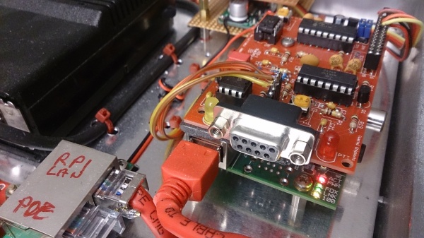
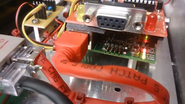
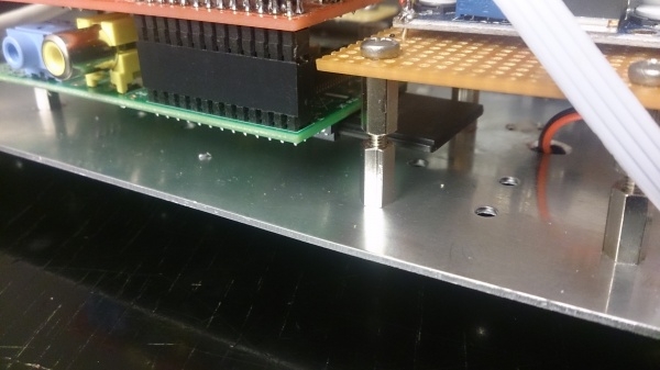
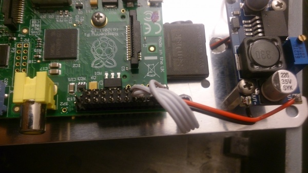
The RPi 1B version which I used has a couple of problems. Notably the USB socket is very high, which gives you a few problems connecting other boards. Stackable shields will easily have shortings wo the ethernet socket. So this is a mechanical issue you will have to solve.
I did it by simply soldering out the USB socket. In case you still need USB connectivity, you will need to attach some angled stacked pins.
As in most of my RPi projects I am using the pin header for power supply. I generally do not use the usb socket, because that seems a little unreliable to me.
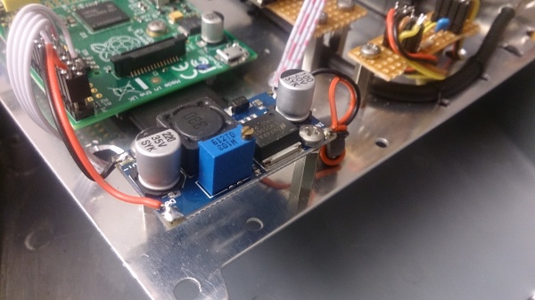
For the power supply I am frequently using DC/DC converters from Ebay, you get them cheap from China.
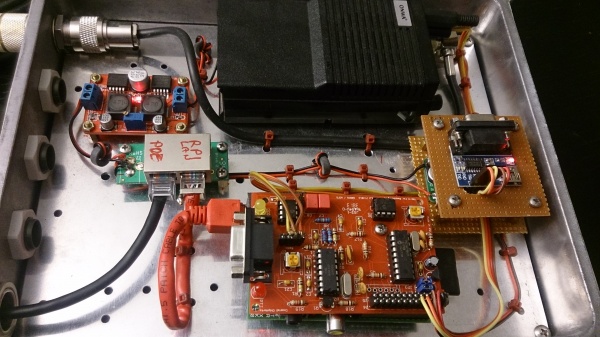
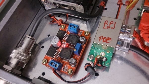
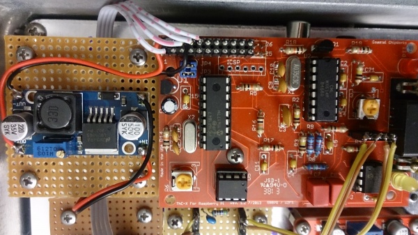
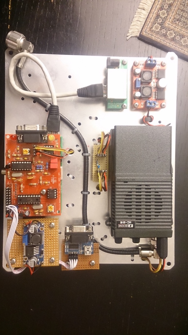
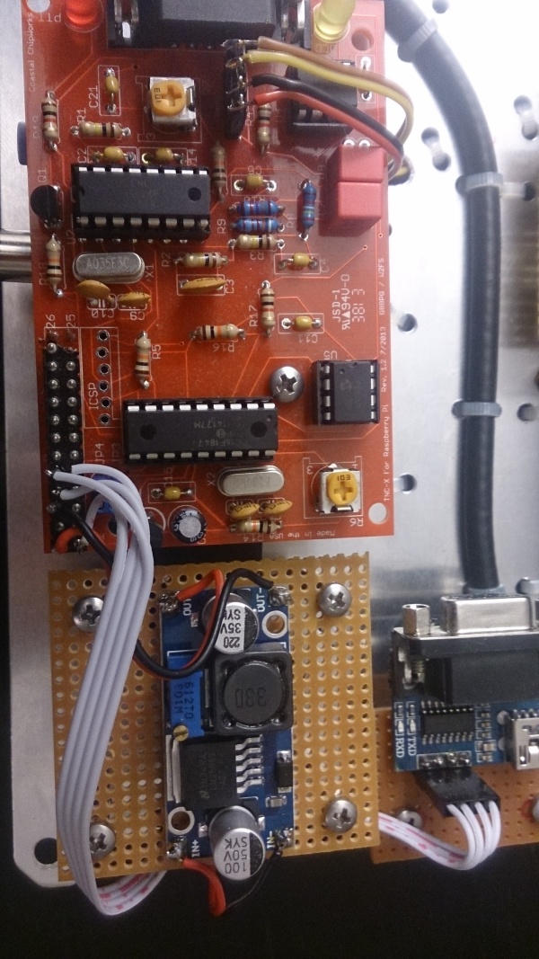
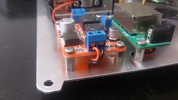
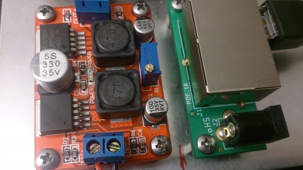
Here in this case I was using two converters, one from any high voltage up to 30V down to 7,5 for the IC2E clone and another one for the step from 7,5 down to 5,0V for the Raspi.
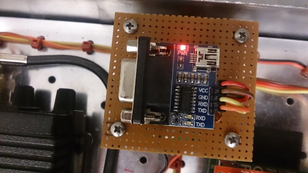
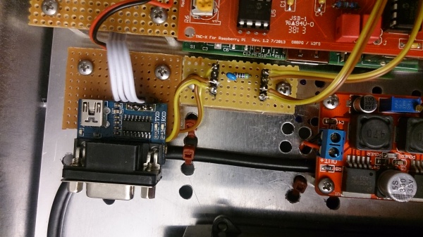
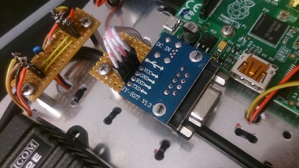
I also attached a serial port socket using a MAX3232 converter, firstly to ensure access to a raw Raspian image, but secondly also for diagnostic actions on the serial line.
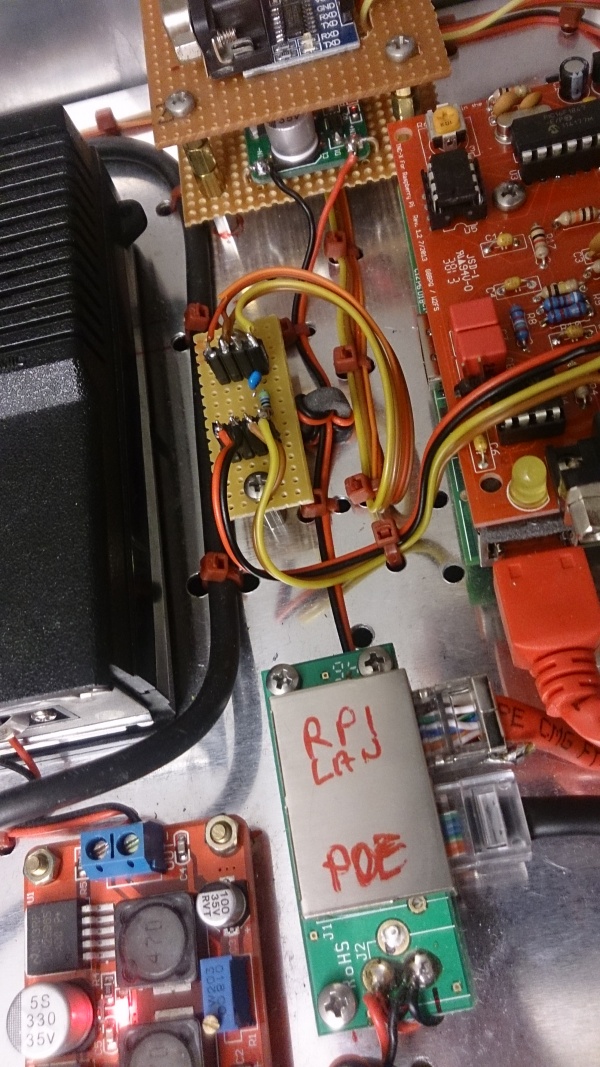
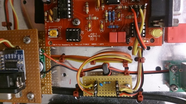
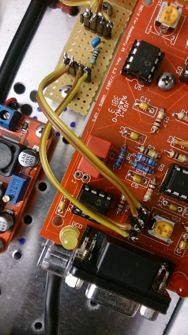
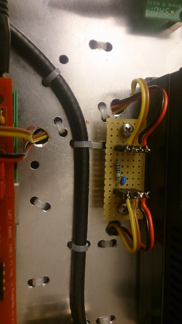
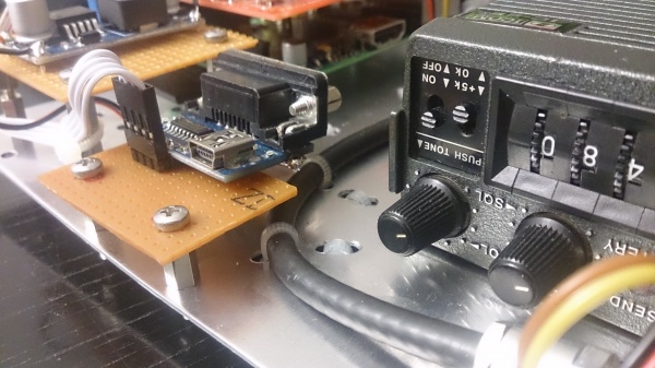
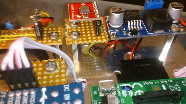
The little pcb in the middle between the Raspberry setup and the radio is a PTT arrangement: The TNC puts a DC voltage on the PTT pin, which must arrive on the TX audio pin of the radio, though, with a considerably high impedance. So a 4k7 resistor will help. The TX audio signal must be given to the same pin, however de-coupled by a capacitor, I am using a 0.1 Microfarad.
Here is some info found on the web about this setup:
 The IC2E can be used successfully on packet. This is how to achieve it.

TNC                             RIG

PTT-----------4.7K-------- TIP OF SMALL JACK

TX AUDIO------0.1MF------- TIP OF SMALL JACK

GROUND-------------------- BODY OF BOTH JACKS

RX AUDIO------------------ TIP OF LARGE JACK

This arrangement works with most TNC2 type clones, but it has not been tried
on the PK88.

Another possibility would be to use a 1 to 1 audio isolating transformer.
This is a suggestion on how to connect it up:

RX AUDIO---------TIP OF LARGE JACK
GROUND-----------BODY OF LARGE JACK
GROUND-----------TRANSFORMER PRIMARY
TX AUDIO---------TRANSFORMER PRIMARY
PTT--------------TRANSFORMER SECONDARY
                 TRANSFORMER SECONDARY---------TIP OF SMALL JACK

When the PTT line goes low, it makes the Tx connection for the IC2E.

Julian G6LOH @ GB7BIL
6 The Radio used
- I am using a IC2E clone: ONWA K-6201. Another alternative is the CT1600, also a IC2E clone.
- Here is the manual: http://www.radiomanual.info/schemi/ICOM_VU/IC-2A_AT_E_user.pdf
- Here is some more insight on the cable type, when connecting a regular TNC (Cable Type 1): http://www.symek.com/d/afskkabel.html
7 The sensor used
For Unit 2, 3, 4, 5 and possibly some more I decided to use a BMP085 / BMP180 sensor breakout board in order to generate some weather related data.
Here is the datasheet: https://www.adafruit.com/datasheets/BST-BMP180-DS000-09.pdf
Here is some background information:
- Fundamentals: http://www.netzmafia.de/skripten/hardware/RasPi/RasPi_I2C.html
- good: https://www.kompf.de/weather/pibaro.html
- also good: http://tutorials-raspberrypi.de/raspberry-pi-und-i2c-luftdrucksensor-bmp180/
- also good: https://www.sparkfun.com/tutorials/253
One important issue that is not normally described in these tutorials: You need to enable I2C in the /boot/config.txt file. Occasionally it is not the line
dtparam=i2c_vc=on
but
dtparam=i2c_arm=on
in order to activate I2C: http://stackoverflow.com/questions/32021924/raspberry-pi-2-cannot-enable-dev-i2c-0
Once you got the sensor connected as described in the manuals, detect it:
i2cdetect -y 1
and it should show up as "77":
     0  1  2  3  4  5  6  7  8  9  a  b  c  d  e  f
00:          -- -- -- -- -- -- -- -- -- -- -- -- --
10: -- -- -- -- -- -- -- -- -- -- -- -- -- -- -- --
20: -- -- -- -- -- -- -- -- -- -- -- -- -- -- -- --
30: -- -- -- -- -- -- -- -- -- -- -- -- -- -- -- --
40: -- -- -- -- -- -- -- -- -- -- -- -- -- -- -- --
50: -- -- -- -- -- -- -- -- -- -- -- -- -- -- -- --
60: -- -- -- -- -- -- -- -- -- -- -- -- -- -- -- --
70: -- -- -- -- -- -- -- 77
Then you can proceed to download Lady Ada's code examples:
git clone https://github.com/adafruit/Adafruit-Raspberry-Pi-Python-Code.git
and then try it out:
cd Adafruit-Raspberry-Pi-Python-Code/Adafruit_BMP085
./Adafruit_BMP085_example.py
Temperature: 25.29 C
Pressure:    974.22 hPa
Altitude:    530
Hooray!
Now you can start to read it out via a script and add it to the APRX configuration.
8 Part list and worktime
Prices in EURO
- 55.- outdoor case http://www.amazon.de/gp/product/B007I0C01M?psc=1&redirect=true&ref_=oh_aui_detailpage_o02_s00
- 35.- Raspberry Pi B
- 10.- 32 GB SD Card
- 20.- The Radio: IC2E
- 5.- 2x DC/DC voltage converter http://www.ebay.de/itm/191003232980
- 35.- TNC-X Pi
- 12.- N to N coax feedthrough
- 5.- big metal feedthrough for LAN cable
- 2.- level shifter for serial port
- 15.- BMP085
- 2.- 2 ferrite cores
- 2.- metal risers M3
- 2.- stainless screws M3
- 2.- collar nuts M3
- 2.- multipin connector m, f
- 4.- wires red/black yellow/brown
- 1.- resistor 470 Ohm, capacitor 0,1uF
- 1.- cable straps (amount depends on setup)
- 4.- passive PoE injector http://www.amazon.de/PoE-Passiv-Injector-PowerOverEthernet-Spannungsversorgung-WRAP-Boards/dp/B00FXOH4C0/ref=sr_1_12?ie=UTF8&qid=1458423972&sr=8-12&keywords=poe+injector
- blind plugs to fill the holes in the case
total: ~200 Euro per unit
worktime: 6 hours
9 Configuration
Beforehand, let me refer to the following documentations of the configuration of the serial port:
- http://www.netzmafia.de/skripten/hardware/RasPi/RasPi_Serial.html
- http://www.auetal-online.net/page3,0,0.xhtml
Change cmdline.txt:
root@airgate:~# cat /boot/cmdline.txt
dwc_otg.lpm_enable=0 console=tty1 root=PARTUUID=03addd43-02 rootfstype=ext4 fsck.repair=yes elevator=deadline rootwait
Disable agetty from grabbing the console and stop it
systemctl stop serial-getty@ttyAMA0
systemctl disable serial-getty@ttyAMA0
systemctl mask serial-getty@ttyAMA0.service
Here's the manual: http://ham.zmailer.org/oh2mqk/aprx/aprx-manual.pdf
- Note that it is really important to set jumpers Nr. 3 and Nr. 4. Otherwise you won'r receive anything and you will not be able to transmit either.
- I was downloading the following APRX version:
wget http://ham.zmailer.org/oh2mqk/aprx/aprx_2.08.593-1_armhf.deb
Here's the APRX config:
mycall  DB0HSR-1
myloc lat 4859.93N lon 01205.59E
<aprsis>
passcode 12345
server    rotate.aprs2.net
</aprsis>
<logging>
pidfile /var/run/aprx.pid
rflog /var/log/aprx/aprx-rf.log
aprxlog /var/log/aprx/aprx.log
</logging>
<interface>
  serial-device /dev/ttyAMA0  19200 8n1    KISS
  callsign     $mycall  # callsign defaults to $mycall
  tx-ok        false    # transmitter enable defaults to false
  #telem-to-is  true # set to 'false' to disable
</interface>
<beacon>
beaconmode both
beacon symbol "I&" $myloc comment "Tx-iGate Raspberry/TNC-X/APRX"
</beacon>
10 Future Plans
So this project really worked well, and APRX allows transmitting, so that is really a great benefit. I will try to extend this project by the following terms:
- build two more of them, provide them to DB0MHB and to DB0KN and create greater coverage
- add some telemetry with a temperature and humidity readout. I will need to think about the connection, because I removed the USB socket for space reasons, as you can see on the pictures below.
11 Images
11.1 Unit 1
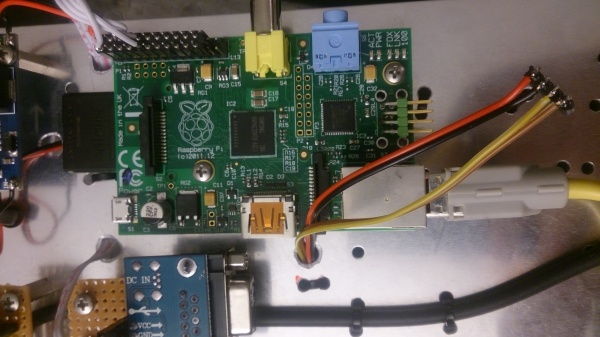
The pictures below show the following modifications:
- The USB port, formerly just de-soldered was led out through angled pins.
- Introduction of some PTT logic that works with the IC2E type of radios (see above)
- Finally got the cabling right... It now transmits. That is what I wanted it to do.
11.2 Unit 2
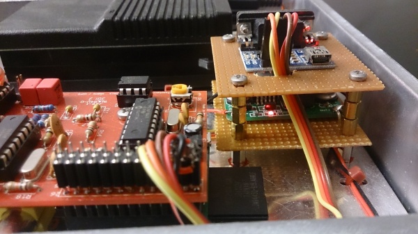
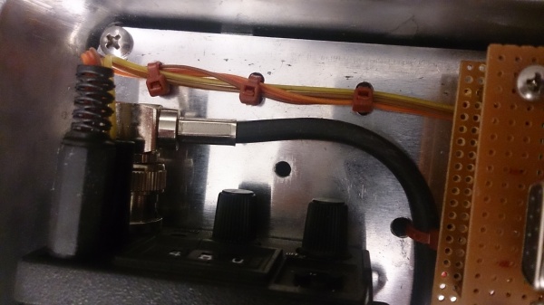
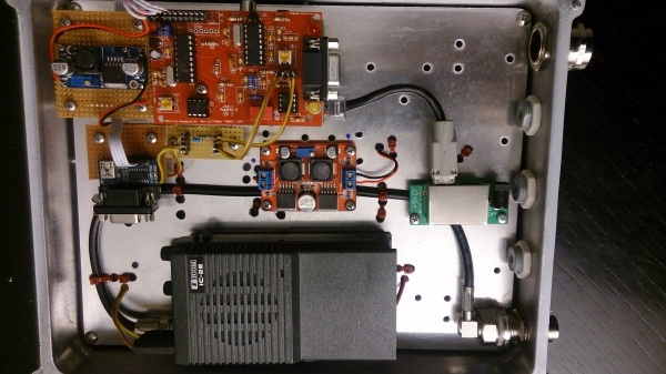
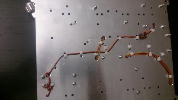
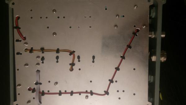
In Comparison to unit 1 I decided to route many of the DC and NF cables on the bottom side of the mounting plate. The entire setup looks more ordered and the shielding may be a bit better. But this is just a guess as I have not yet noticed any problems.
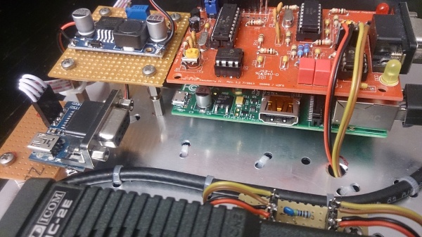
Placing the DC converter on top also brought me some problems: It is not possible to remove the MMC card without dismounting the plate from the box. Though, it gave me some more space in the top section.
And I found another way to mount the Serial converter: I just soldered the converter on a board via the four header pins.
And I also left the barrel DC converter on the injector. This allows to feed 24V DC with a plug type power supply.
11.3 Unit 3
Changes:
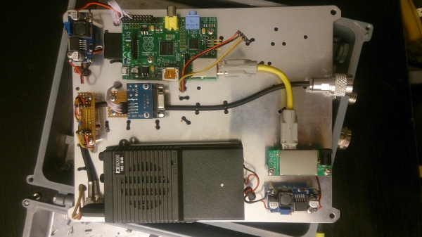
- Unit 3 holds the cables on the lower side, except the coax. This concept is like in unit 2, but it consequently places the DC and audio cables on the lower side. And the arrangement is changed a little, so that serial access is possible a little easier.
- LAN comes in by the middle, mainly because the box I used this time, had it in the middle.
- Therefore, HF comes in at the right, no longer at the left. This has the advantage that the IC2E's power supply (DC/DC converter) can be placed right under the radio. In front of the DC converter there's the right position for the LAN/DC coupler. And the other DC converter goes right at the top. Reason for this is that the wires that possibly hold ripple, can be very short before they go into the consumer.
- This setup allows enough space in the middle, so that a serial debug plug (serial/USB converter) can be attached without problems.
- Like in unit 2, the upper DC converter (5V for the Raspi) is mounted quite high so that the SD card can be handled easily.
- Like in unit 2, Raspian Jessie was used.
11.4 Unit 4
The first photos still do not show the TNC-X. It will be completed as soon as it arrives here.
Changes:
- Lan also comes into the case in the middle.
- Cleaner Cabling
- PTT/MIC feed is now located on the top of the backpanel.
- Serial debug interface is now mounted rather high up, and the cable is also lead on the rear of the backpanel.
- DC converters are not using stipline through-hole PCBs any more because I found DC converters with onboard mounting holes that can be directly mounted to the backpanel. It saves a lot of space.
- Like in unit 2 and 3, Raspian Jessie was used.
11.5 Unit 5
This unit is the last unit from this series. Starting with this unit, I decided to upgrade all the units 2-5 with the BMP085 or ther BMP180 sensor breakout board. The details of the installation are described above.
