Upgrade an ASUS WL-500gP to control my RIG: Unterschied zwischen den Versionen
Dl8rds (Diskussion | Beiträge) |
Dl8rds (Diskussion | Beiträge) |
||
| Zeile 1: | Zeile 1: | ||
| − | I have now purchased already | + | I have now purchased already my second ASUS WL-500gP, because they are really well equipped and they make an excellent platform to do some really thrilling experiments. The first ASUS goes to my friends from DB0MHB, and the second will control my own radio room and provide some more functions to our LAN. |
== Access the root shell through the serial port == | == Access the root shell through the serial port == | ||
| − | This requires to purchase or build a level shifter. | + | This requires to purchase or build a level shifter. |
| + | == Flash it == | ||
| + | |||
| + | |||
| + | Flashing OpenWRT to the ASUS WL500gP | ||
== Build a new case == | == Build a new case == | ||
Since I plan to do so many experiments and enhancements to the router, I need a new case. I have developed a technique to build new cases with one-sided PCBs. | Since I plan to do so many experiments and enhancements to the router, I need a new case. I have developed a technique to build new cases with one-sided PCBs. | ||
Version vom 5. September 2008, 01:50 Uhr
I have now purchased already my second ASUS WL-500gP, because they are really well equipped and they make an excellent platform to do some really thrilling experiments. The first ASUS goes to my friends from DB0MHB, and the second will control my own radio room and provide some more functions to our LAN.
Inhaltsverzeichnis
1 Access the root shell through the serial port
This requires to purchase or build a level shifter.
2 Flash it
Flashing OpenWRT to the ASUS WL500gP
3 Build a new case
Since I plan to do so many experiments and enhancements to the router, I need a new case. I have developed a technique to build new cases with one-sided PCBs.
- Photographs to follow
4 Integrate two level shifters into the new case
The new case will also contain according interfaces to connect to the serial ports on the board.
- Photographs to follow
5 Use another USB interface
The VIA USB controller chip actually has four pinout sets for USB interfaces. The first sub-experiment aims to connect at least one of them and to provide fixed storage over a USB memory stick.
- Photographs to follow!
6 Integrate a USB hub into the newly built case
Since I plan to connect a multitude of devices, I need more than the few slots.
- Photographs to follow
7 Build an electricity switch
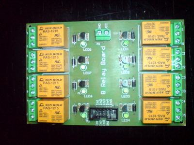
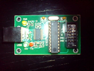
Recently I have purchased a 8 relay card from a seller from Bulgaria which is controlled through an ATMEL Tiny chip, which again is accessible through a USB2Serial FTDI chip. Since I have compiled FTDI support into my OpenWRT image, I can access the ATMEL.
The control is fairly simple: I just need to set the interface speed to 9600 Bit/s and send a certain combination of characters to the serial device /dev/ttyUSB0.

