QO-100 Ground Station: Unterschied zwischen den Versionen
Dl8rds (Diskussion | Beiträge) (→Test Management) |
Dl8rds (Diskussion | Beiträge) (→HackRF Transmit 2,4GHz using GNURadio with Power Amplifier) |
||
| Zeile 153: | Zeile 153: | ||
Check if we can drive the power amplifier. See if the 10dBm output is enough or if an intermediate driver is necessary | Check if we can drive the power amplifier. See if the 10dBm output is enough or if an intermediate driver is necessary | ||
| − | Result: 10dBm input at the PA will produce about 5W out. That's enough. | + | Result: 10dBm input at the PA will produce about 5W out. That's enough. |
| + | |||
| + | The following picture is a measurement with 30dB 10W attenuator and 20dB low power attenuator, totalling 50dB attenuation. So TX power is 37dBm. | ||
| + | |||
| + | [[Image:2022-10-02-qo100-tx-test-max-power.png|400px]] | ||
=== PA current at different input voltages === | === PA current at different input voltages === | ||
Version vom 2. Oktober 2022, 01:00 Uhr
Inhaltsverzeichnis
- 1 Scope
- 2 Components
- 3 Circuit Description
- 4 Test Management
- 4.1 GPSDO frequency stability and usage of GPS stability vs GPS disconnected state
- 4.2 GPSDO distance main signal vs first overtone
- 4.3 GPSDO spectral purity
- 4.4 GPSDO 10 MHz signal form assessment
- 4.5 GPSDO signal voltage
- 4.6 Distribution Amplifier output signal quality
- 4.7 Distribution Amplifier distance main signal vs first overtone
- 4.8 Distribution Amplifier Output Phase Difference
- 4.9 HackRF ref clock input
- 4.10 HackRF Reception using RemSDR
- 4.11 HackRF Transmit 70cm using GNURadio
- 4.12 HackRF Transmit 2,4GHz using GNURadio
- 4.13 HackRF Transmit 2,4GHz using GNURadio with Power Amplifier
- 4.14 PA current at different input voltages
- 4.15 PA FWD monitor voltage
- 4.16 PA SWR monitor voltage
- 4.17 48V / 24V Converter Ripple
- 4.18 Bias Tee Controll Voltages
- 4.19 Generate HF via WebGUI
- 4.20 Receive HF via WebGUI
- 5 Images
1 Scope
My first QSO via QO-100 took place on 01.03.2019 with DF6NM at the portable station of my friend Severin DL9SW. Since then I wanted to acquire the capabilities to transmit to the satellite myself and receive it's signals.
In summer 2022 I met a trainee in my company who wanted to learn about satellite communication, and given that I am working in a satellite project for Airbus, it was apparent that there was a chance to build it.
In fact such a project gives me quite a number of topics that I can teach to our trainees:
- Requirements Engineering
- Mechanical Planning
- Electrical Planning
- Electrical Engineering fundamentals
- RF Engineering fundamentals
- Electrical Safety
- Specifics of Satellite Radio Communications
- Electrical Measuring
- Software Defined Radio
- Microcontroller Programming
- Embedded Systems / Embedded Linux (Raspberry Pi)
- Linux System Programming
- Networking
- GUI Design / Browser Engineering
- Quality Assurance (IVV)
- Practical Radio Operations
So this project is rather fruitful.
2 Components
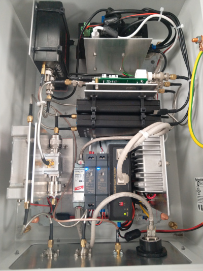
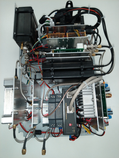
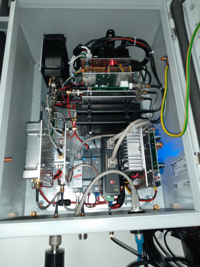
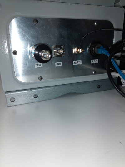
The installation consists of three units:
- The Antenna unit, which is mounted on a pole
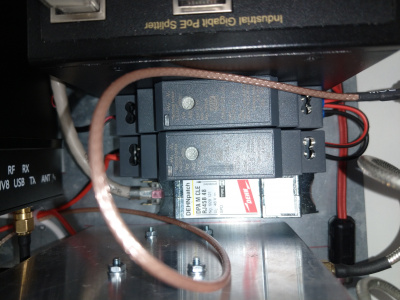
- The main unit, which is mounted below the antenna installation, on the same pole, together with a PoE injector, that resides somewhere inside a house.
- The User workstation. This is just a normal PC, operating Ubuntu Linux (can be Windows too). It is also possible to operate it with an ordinary laptop.
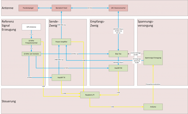
The first two components are displayed in the following diagram:
2.1 Antenna Unit
- WISI Orbit Topline Satelliten Offset Antenne OA85H https://katalog.wisi.de/oa-85-h-18910.html
- Duoband Feed Bamatech für Es'Hail-2/P4-A V2.0 https://www.bamatech.net/antennen/duoband-feed-2-4-10-ghz--Es---hail-2-P4-A--antenna.html?language=de
- Bamatech 40mm Adapterring https://www.bamatech.net/antennen/reduzierring-40-mm-auf-23-mm.html
- Kuhne MKU LNC 10 QO-100 https://shop.kuhne-electronic.de/kuhne/de/shop/neu/MKU+LNC+10+QO100+Verfuegbar+Q22019/?card=1874
- Flachdach Ständer https://www.otto.de/p/premiumx-deluxe-sat-balkonstaender-4x-50x50cm-stahl-1-20m-mast-60mm-plattenstaender-flachdach-staender-fuer-satellitenschuessel-sat-halterung-S0N0S0T0/#variationId=S0N0S0T0WZFT
2.2 Main Unit
- Schneider Electric Spacial NSY3D4320P Spacial Volltür https://www.se.com/de/de/product/NSYS3D4320P/spacial-s3d-vollt%C3%BCr-mit-montageplatte-h400xb300xt200-ip66-ik10-ral7035/
- SCHNEIDER ELECTRIC NSYSFPSC30 - Pole mounting kit https://www.tme.eu/en/details/nsysfpsc30/enclosures-other-accessories/schneider-electric/
- Elektronik Idee Weber Frequency normal (GPSDO) https://www.facebook.com/profile.php?id=100063884658796
- CircuitValley Distribution Amplifier https://www.circuitvalley.com/2018/07/diy-isolated-10mhz-distribution-amp-gpsdo-rubidium-tcxo-reference.html
- 2x GreatScott HackRFOne https://greatscottgadgets.com/hackrf/one/
- 2x NooElec Metal Case for HackRF One https://www.nooelec.com/store/sdr/sdr-addons/hackrf-enclosure.html
- Kuhne KU BT 10 REF Bias-Tee https://shop.kuhne-electronic.com/kuhne/en/shop/eshail/KU+BT+10+REF++Bias+Tee/?card=1885
- DX Patrol QO-100 Power Amplifier https://dxpatrol.pt/produto/power-amplifier/
- RaspberryPi 4B https://www.raspberrypi.com/products/raspberry-pi-4-model-b/
- GeeekPi Raspberry Pi 4 Gehäuse, Raspberry Pi CNC Armor Case mit passiver Kühlung https://www.amazon.de/GeeekPi-Raspberry-Passive-Dissipation-Heatsink-Black/dp/B07WQT1RRZ/
- Arduino Nano V3 https://www.reichelt.de/arduino-nano-v3-atmega-328-mini-usb-arduino-nano-p142943.html
- PENGLIN 1PCS 4 Kanal 5V Relais Module https://www.amazon.de/PENGLIN-Relais-Optokoppler-Trigger-Raspberry/dp/B0B42765M5
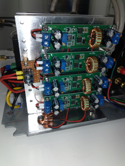
- 4x Akozon DC-DC Buck Converter Voltage Regulator DC-DC Buck Step Down Input Max 60V https://www.amazon.de/Akozon-Converter-Spannungsregler-Einstellbares-Wandlermodul/dp/B07H5MC6V3
- SUPERNIGHT DC DC Buck Converter watertight Voltage Konverter 48V to 24V https://www.amazon.de/SUPERNIGHT-Converter-Wasserdicht-Spannung-Konverter/dp/B0BG4TCPVK
- AZDelivery 1-Relais 5V KY-019 Modul https://www.az-delivery.de/products/relais-modul
- 30cm Micro USB Kabel Kurz [5 Stück]
- DIGITUS PoE++ Splitter - IEEE802.3af/at/bt - Gigabit Ethernet https://www.amazon.de/DIGITUS-Professional-Industrieller-Splitter-abw%C3%A4rtskompatibel/dp/B07FDT1BMQ
- DIGITUS PoE+ Injektor - IEEE802.3at - Gigabit Ethernet - 60 Watt - max. 48 Volt - PoE Modus A & Modus B https://www.amazon.de/DIGITUS-Professional-Injector-802-3at-Output/dp/B01ARHCFOO
- 15V DIN Rail power supply https://www.elektrokon.de/15-vdc-1-a-15-watt-mean-well-hdr-15-15-hutschienen-netzteil-din-rail_90795_14251
- 5V DIN Rail power supply https://www.distrelec.de/en/din-rail-type-dc-dc-converter-5v-3a-15w-adjustable-mean-well-ddr-15g/p/30134120
- Dehn Patch RF45 Overvoltage Protection https://www.reichelt.de/pl/en/dehnpatch-surge-protection-with-2-rj45-sockets-dpa-m-cle-rj45b-p254660.html
- High Side Current Monitor INA226 https://www.ti.com/lit/ds/symlink/ina226.pdf
- 3x OneWire Temperatire DS18B20 https://datasheets.maximintegrated.com/en/ds/DS18B20.pdf
- GPS Mouse receiver SMA https://www.amazon.de/Aktive-GPS-ANTENNE-SMA-Anschluss-Receiver-Module/dp/B01A5EI0SE
- Amphenol Military Grade Plug https://www.distrelec.de/en/cable-plug-rj45-amphenol-military-and-aerospace-rjf-6b/p/14242003
- Amphenol Military Grade Socket https://www.distrelec.de/en/appliance-socket-rj45-amphenol-military-and-aerospace-rjf-71b/p/14242001
2.3 User Unit
- MPC-4LAN-N3700 MiniPC
- Kingston KC600 256G SSD SATA3 mSATA - SKC600MS/256G
- Crucial CT102464BF186D 8GB Speicher (DDR3, 1866 MT/s, PC3-14900, SODIMM, 204-Pin)
- Rode USB-NT Microphone
- USB speakers
- MikroTik RBD52G-5HACD2HND-TC Wireless Access Points für hAP ac2
- USB Port Extension
- USB Keyboard
- USB Mouse
- Screen
3 Circuit Description
Generally I wanted to have a QO-100 transceiver that can be set up at a distant place with an internet connection so that I can access it through my VPN. It should be capable to work full duplex and the user interface should be just a Web GUI, so that using a simple browser would allow me to operate it from almost anywhere.
The configuration that was most likely to fulfill all these requirements was the RaspberryPi 4B based RemoreSDR software from André Buhart F1ATB. André also supports the usage of two HackRFs for full duplex and explicitly describes such a setup on his website: https://f1atb.fr/index.php/2022/05/21/remote-sdr-v5-raspberry-4b-or-orange-pi-image-installation/
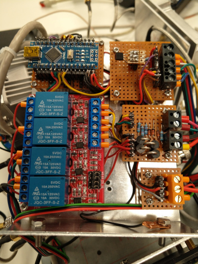
The antenna unit is designed to downconvert the RX signals immediately to a reasonable frequency (10 GHz -> 430 MHz). The Kuhne LNC is actually for operation with analog 70cm devices, but it serves perfectly fine with a HackRF also. In order to produce the necessary voltages, a bank of DC buck converters was used. The needed voltage will then be chosen with a 4 module relay bank. The control of the relay bank, but also other parts of the entire installation is done by an Arduino which is hooked up serially to the RaspberryPi. This Arduino gives me full remote monitoring and station management capabilities.
Most interesting is the Kuhne Bias Tee, because one of the most challenging problems is frequency stability. My installation will e mounted outside with sunshine heating up all the arrangement. So frequency drift will be a major issue. The Kuhne Bias Tee will allow to insert a 10 MHz reference signal and send it up to the antenna. Off course I have more 10 MHz consumers, which are the HackRFs. So consequently I needed a distribution amplifier, which I found from CircuitValley, which has four ports. The generation of the 10 MHz signal will be done by a Weber GPSDXO disciplined oscillator.
3.1 Control Circuit
Here is my controller program:
asdasdasd
3.2 Software
The software I am using comes from André Buhart. It is well usable and does it's job. Note that André does not put great attention on station usage security, so I recommend to use it only in a trusted environment, i.e. within your VPN or in your home LAN. There however it is a really fabulous piece of operation software.
4 Test Management
Test Management is an important part in Quality Assurance and for every project in general. In order to assure that the device is working properly, the following tests were carried out:
4.1 GPSDO frequency stability and usage of GPS stability vs GPS disconnected state
Check how the GPSDO works without a GPD discipline and after it is connected
4.2 GPSDO distance main signal vs first overtone
Check the dB distance of the 10 MHz signal towards the first overtone
4.3 GPSDO spectral purity
Check if the signal produces only clean 10 MHz (and maybe overtones) but nothing else
4.4 GPSDO 10 MHz signal form assessment
Check if it is a proper sine wave.
4.5 GPSDO signal voltage
Check the voltage and wave form of the outputs and see if there are no bad things on the signal.
4.6 Distribution Amplifier output signal quality
Check the voltage and wave form of the outputs and see if there are no bad things on the signal.
4.7 Distribution Amplifier distance main signal vs first overtone
Check if the distance to the first overtone in terms of signal power is big enough
4.8 Distribution Amplifier Output Phase Difference
Ensure that there is no phase difference on the outputs
4.9 HackRF ref clock input
hackrf-debug --si5351c -n 0 -r -d <serial number>
0x01 bedeutet: GPSDO Signal wird erkannt und verwendet
4.10 HackRF Reception using RemSDR
See if we can receive signals generally
4.11 HackRF Transmit 70cm using GNURadio
Generate a carrier and see if we can produce something at all and if it arrives at an antenna
4.12 HackRF Transmit 2,4GHz using GNURadio
See if we can generate a reference signal at the target frequency
4.13 HackRF Transmit 2,4GHz using GNURadio with Power Amplifier
Check if we can drive the power amplifier. See if the 10dBm output is enough or if an intermediate driver is necessary
Result: 10dBm input at the PA will produce about 5W out. That's enough.
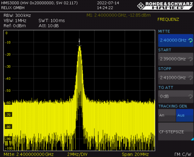
The following picture is a measurement with 30dB 10W attenuator and 20dB low power attenuator, totalling 50dB attenuation. So TX power is 37dBm.
4.14 PA current at different input voltages
Measure current at 10V, 20V, 30V
Result: Decision to drive it constantly with 24V
4.15 PA FWD monitor voltage
See if the monitor voltage that comes out of the PA (nominal between 0-4V) acts as expected
Result: 2,2V auf Forward-Pin bei 37dBm Sendeleistung
4.16 PA SWR monitor voltage
See if there is a SWR voltage. Unfortunately a Calibrated Mismatch Load is too expesive.
Result: We do see a voltage, bu it is small. 0,57V Spannung auf SWR-Pin bei 37dBm Sendeleistung
4.17 48V / 24V Converter Ripple
Check ripple voltage in PA input voltage
Result: Smaller than 0,2 % (good)
4.18 Bias Tee Controll Voltages
Check if the voltages produced by the controller board arrive at the bias tee.
Result: OK
4.19 Generate HF via WebGUI
Check if all of the transmit path works properly. Talk into the notebook microphone and listen on a handheld radio on 70cm. Check if the audio is good and if the delay is still acceptable.
Result: Works
4.20 Receive HF via WebGUI
Check if all of the receive path works properly. Talk into the handheld radio's microphone and listen to the signal on the WebGUI. Check if the audio is good and if the delay is still acceptable.
Result: Works
