Upgrade an ASUS WL-500gP to control my RIG
I have now purchased already my second ASUS WL-500GP, because they are really well equipped and they make an excellent platform to do some really thrilling experiments. The first ASUS goes to my friends from DB0MHB, and the second will control my own radio room and provide some more functions to our LAN.
Inhaltsverzeichnis
- 1 Access the root shell through the serial port
- 2 Flash it
- 3 Build a new case
- 4 Integrate two level shifters into the new case
- 5 Use another USB interface
- 6 Integrate a USB hub into the newly built case
- 7 Build an electricity switch
- 8 Build a case for the switch
- 9 Turn my Asus router into a packet relay
1 Access the root shell through the serial port
This requires to purchase or build a level shifter.
2 Flash it
I have built a level shifter some time ago, and I have flashed my first ASUS with it, but actually flashing the ASUS is so easy you don't even need a level shifter.
- You need a TFTP server setup on your workstation and provide the flash image there. Here's a description how to set up a TFTP server.
- On the back side of the ASUS there's a reset button. Keep it pressed, unplug the device and keep it pressed a few more seconds until an LED starts blinking. Now the ASUS is in TFTP recovery mode. The BIOS is activated for the IP 192.168.1.1. Make sure this IP is not active elsewhere in your network. Often this IP is taken as router IP, so better unplug your main router.
Then enter the following lines:
bash-shell > tftp 192.168.1.1
tftp> binary
tftp> trace
tftp> put openwrt-brcm-2.4-squashfs.trx
Needless to say that the openwrt-brcm-2.4-squashfs.trx image must be in the current working directory, otherwise the tftp will not find it.
You'll get a lot of debug messages and you'll see when the transfer is read. Then WAIT SIX MINUTES!!!!! This is the time the ASUS takes to write the flash image to the flash disk. If you interrupt, your router will be bricked and there's no way to get it working ever again but by attaching a serial console over a level shifter.
3 Build a new case
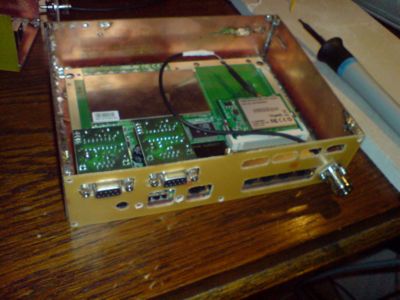
Since I plan to do so many experiments and enhancements to the router, I need a new case. I have developed a technique to build new cases with one-sided PCBs.
Please note the N-connector on the right side. I decided to substutite the horribly annoying Reverse-SMA. There are no real good adapters for this type of plug. I needed a standard plug to connect to standard cables.
4 Integrate two level shifters into the new case
The new case will also contain according interfaces to connect to the serial ports on the board.
- see the photo above.
5 Use another USB interface
The VIA USB controller chip actually has four pinout sets for USB interfaces. The first sub-experiment aims to connect at least one of them and to provide fixed storage over a USB memory stick.
- Photographs to follow!
6 Integrate a USB hub into the newly built case
Since I plan to connect a multitude of devices, I need more than the few slots.
- photographs to follow
7 Build an electricity switch
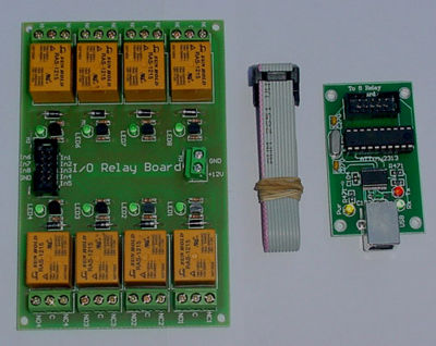
Recently I have purchased a 8 relay card from a Ebay seller from Bulgaria which is controlled through an ATMEL Tiny chip, which again is accessible through a USB2Serial FTDI chip. Since I have compiled FTDI support into my OpenWRT image, I can access the ATMEL.
The control is fairly simple: I just need to set the interface speed to 9600 Bit/s and send a certain combination of characters to the serial device /dev/ttyUSB0.
Controlling the relays is extremely simple. You just need to enter the following command:
echo "FF 01 00" > /dev/ttyUSB0 # switch relay nr. 1 OFF
echo "FF 01 01" > /dev/ttyUSB0 # switch relay nr. 1 ON
echo "FF 08 00" > /dev/ttyUSB0 # switch relay nr. 8 OFF
echo "FF 08 01" > /dev/ttyUSB0 # switch relay nr. 8 ON
8 Build a case for the switch
- Photographs to follow
9 Turn my Asus router into a packet relay
Here is a good description:
Yes, it's working: Using the ASUS WL-500gP as a APRS digi

