Experiments with Trimble's Lassen IQ
Inhaltsverzeichnis
1 Preamble
This place is still a storeground for ideas. Currently, I'm still far away from starting to work. This is also due to some other projects which clearly enjoy more priority.
2009-11-04 This projekt is still a storeground for ideas and will remain so. I got some more stuff in the meantime, but I also got some ingredients ready for some other idea related to this project:
Building an extremely small ARPS Tracker
2 Here comes the LassenIQ
The Lassen IQ is a GPS receiver that is extremely power efficient. Here are some links:
Here's a little theory on satellite navigation:
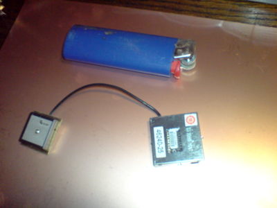
And here it is:
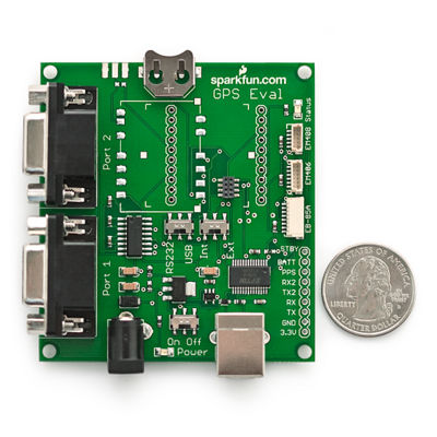
An Evaluation Board from SparkFun:
But I also read that the LassenIQ is somewhat outdated technology in the meantime, so I also purchased another GPS receiver module, which nicely fits on the same experimental board:
http://www.sparkfun.com/commerce/product_info.php?products_id=465
The 20 Channel EM-406A SiRF III Receiver with Antenna is far more sensitive, has more channels and consumes less energy. And it is far more compact. And it delivers its data by default in the NMEA format.
This will be another ingredient for my low power APRS tracking transmitter.
3 APRS-Tracker
The challenge is to build a high performance tracker as power efficient and as space-efficient as it can be.
Ingredients:
- Trimble LassenIQ
- Trimble ANT
- OpenTracker SMT
3.1 The OpenTracker SMT
Here's a photo of the OpenTracker SMT. It's really small:
The tracker's inner values:
- Voltage: DC 6.5 to 28V unregulated or 5V DC regulated
- Current: 8 mA idle, 20 mA transmitting Max 200 mA @ 5 V available for GPS
- Modes: 1200 bps AFSK (send and receive); 300 bps AFSK, PSK31 (send only)
- Radio Connector: pin header
- Serial Connector: pin header
- Dimensions: 31mm x 18mm x 5mm
- GPS interface: NMEA in/out
Pinout:
Pin  Name   Funktion
1    5VIN     Geregelter 5-Volt-Eingang
2    RxD      RS-232 Data in der (vom GPS oder Computer)
3    1Wire    Dallas 1-Draht-Bus für externe Sensoren
4    AOUT     Audio-Ausgang an Radio
5    ADC5     Analog-Eingang
6    T1CH1    Timer-Kanal
7    ADC6     Analog-Eingang
8    RST      Reset (active low)
9    ADC7     Analog-Eingang
10   IRQ-     Transmit-now, Profil wählen, oder Zähler
11   ADC8     Analog-Eingang
12   ADC9     Analog-Eingang
13   AIN      Audio-Eingang von Radio
14   ADC4     Analog-Eingang
15   ADC3     Analog-Eingang
16   TXD      RS-232 Data aus
17   rot      rot LED-Ausgang
18   grün     grün LED-Ausgang
19   ADC2     Analog-Eingang
20   ADC1     Analog-Eingang
21   PTT      Push-to-talk-Signal an Radio
22   REGOUT   Regulator-Ausgang - 5 Volt
23   GND      Ground
24   REGIN    Regulator-Eingang - 6,5 bis 28 Volt
3.2 Pinouts for the LassenIQ
Pin-Nr.  	Funktion  	Beschreibung
1 	TXD A 	Sendeleitung der seriellen Schnittstelle
2 	GND 	Masse
3 	RXD A 	Empfangsleitung der seriellen Schnittstelle
4 	PPS 	Puls pro Sekunde
5 	reserviert 	nicht verbinden
6 	reserviert 	nicht verbinden
7 	Vcc 	3,3±0,3V (ca. 33mA)
8 	Batterie 	2,5-3,6V (ca. 19μA)
This project could serve to implement a live Openstreetmap logger... Let's see.
4 Homebrew Data Logger
Actually, this might be my first ARDUINO project.
A glance at the others:
- http://nomadness.com/gps-datalogger
- http://elmicro.com/de/arduino.html
- http://www.mikrocontroller.net/topic/72507
- http://www.mikrocontroller.net/topic/68257#new
- http://www.embedtronics.com/GPS/lassenSQ.html
I'm still unsure how to do it... but there is that fantastic GPS shield from Watterott now...:

