8 Port Passive PoE Injector, Managed and Fused
Inhaltsverzeichnis
1 Project Scope
My parents' house is widely equipped with Mikrotik routers and other passive PoE powered hardware. So a centralized power distrution seems reasonable. However, passive PoE injectors like the one from Intellinet have one considerable problem:
They use a powerful PSU, capable of delivering a high current to a single port in case of a short circuit on the cable, inevitably causing a fire.
So I wanted to have a PoE injector that has a per-port fuse, however with remote diagnostic capability on broken fuses, as I can always easily ask my parents to exchange a broken fuse. I was not ale to find such a device on the market, so I built it myself.
Additional features:
- Web Interface
- Current port switching status
- Fuse status
- Syslog interface for event reporting
- Switching events
- Fuse failure events
- External powering (24V) from UPS / Battery
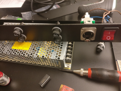
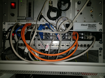
I was using the Intellinet 12 port network patchpanel first, but I found that it had no fuses, so I discontinued to use it:
2 Component List
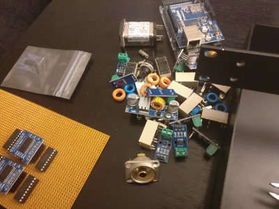
- SanDisk Micro Secure Digital (Micro SD) Speicherkarte 32 GB: Amazon: 15 €
- NEUTRIK Cinch Einbaubuchse, sw, NF2D0: Amazon: 12 €
- Neutrik NE8FDP RJ45 Durchgangs-Einbaubuchse, vernickeltes D-Gehäuse: Amazon: 9 €
- ah 19" Parts 87407V 19" Leergehäuse 1 HE mit Lüftungsschlitzen: Amazon: 44 €
- Netzdrossel: 5 €
- 10x Sicherungshalter: 25 €
- 8x Feinsicherung 500mA: 5 €
- Feinsicherung 1A, Feinsicherung 6A, 1 €
- Schrumpfschlauch-Set: 15 €
- Lochraster-Platinen: 5 €
- Stiftleisten, Buchsenleiten: 15 €
- 8x Injektoren: 30 €
- Beleuchteter Hauptschalter: 3 €
- Kabelführungen, klebend: 15 €
- Kabelbinder: 5 €
- Netzteil Meanwell 24V 150W (6,5A) MW LRS-150F-24: 25 €
- 2x DC-DC-Spannungswandler: 10 €
- 14 Ringkerne: 15 €
- 8x bistabile Doppelrelais 5V: 80 €
- BME280 Sensor: 15 €
- Cinch Stromversorgungskabel: 5 €
- Kabelschuhe: 5 €
- 2x Gravitech 8 Channel ADC I2C, Mouser USA: 20 €
- 20x R, 50 kOhm, 8x 20kOhm usw: 5 €
- 1x PCF8575: 3 €
- 1x PCF8574: 3 €
- 1x Gravitech I2C-TRN: 10 €
- NanoPi Neo2: Amazon, 37 €
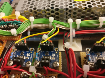
- 8x Adafruit INA169 : 80 €
- Ethernet cable: 3 €
- Screw Headers: 10 €
530 €
Unfortunately including components I built in, found crappy and removed again, the project price is somewhat at about 800 €.
Datasheets:
- Datei:Gravitech-i2c-adc.pdf
- Datei:Pcf8575.pdf
- Datei:Pcf8574.pdf
- Datei:Uln2803.pdf
- Datei:Panasonic relay.pdf
- Datei:Acs712.pdf
- Datei:Ina169.pdf
Websites:
3 References
- Reading a value from the I2C port with an Arduino - with a note why 0x48 and 0x90 are kind of related. You see that in sample code snippets on the Gravitech I2C ADC board.
- Talking to the network with an Arduino - with some notes on I2C
- Some really good information on how to access the PCF type port expanders: http://electronicsbyexamples.blogspot.de/2014/06/io-expander-pcf8574-with-raspberry-pi.html
4 Sensor Access
Once again my experience hit me hard that Arduino type controllers are only really good if their usage is exclusively related to reading out values. They don't excel very much as web platforms. Given that they are rather big compared to those recent NanoPi Neo type minicomputers, I have taken the decision to prefer them in any cases in which network programming is part of a project. There is no price advantage in an Arduino, but there is a lot of disadvantage in limited debugging flexibility.
The I2C part was not so bad after getting the cabling right. After some time, all the I2C slaves were visible:
root@poeinjector:~# i2cdetect -y 0
     0  1  2  3  4  5  6  7  8  9  a  b  c  d  e  f
00:          -- -- -- -- -- -- -- -- -- -- -- -- --
10: -- -- -- -- -- -- -- -- -- -- -- -- -- -- -- --
20: 20 -- -- -- -- -- -- 27 -- -- -- -- -- -- -- --
30: -- -- -- -- -- -- -- -- -- -- -- -- -- -- -- --
40: -- -- -- -- -- -- -- -- -- -- 4a 4b -- -- -- --
50: -- -- -- -- -- -- -- -- -- -- -- -- -- -- -- --
60: -- -- -- -- -- -- -- -- -- -- -- -- -- -- -- --
70: -- -- -- -- -- -- -- 77
The addresses are:
- 20: PCF8575 16 channel
- 27: PCF8574 8 channel
- 4a: Gravitech I2C ADC based on TI ADS7828 http://www.ti.com/lit/ds/symlink/ads7828.pdf
- 4b: Gravitech I2C ADC based on TI ADS7828
- 77: BME280 Bosch Environmental sensor
Little explanation about the PCF8575 and the PCF8574: I am using the 8 channel PCF8574 to detect the relay switch state and the 16 channel PCF8575 to swith the bistable latching relays. For this reason I will take the PCF8574 readout to control the success of the PCF8575 switching operations.
So since the relays are bi-stable / latching, I must not set both rows in the PCF7585 to ff, but only one at a time. And I can easily swith off power after the switching is done.
root@poeinjector:~# i2cset -y 0 0x20 0xff 0x00; i2cset -y 0 0x20 0x00 0x00
(everything off) and correspondingly for the most right (number 7 and 8):
root@poeinjector:~# i2cset -y 0 0x20 0x00 0x1c; i2cset -y 0 0x20 0x00 0x00
And reading out the relay state works like this:
root@poeinjector:~# i2cget -y 0 0x27
0x1c
root@poeinjector:~# i2cset -y 0 0x20 0x00 0xff; i2cset -y 0 0x20 0x00 0x00
root@poeinjector:~# i2cget -y 0 0x27
0xff
The relay numbering logic equals this:
Nr 1 - 0x01
Nr 2 - 0x02
Nr 3 - 0x04
Nr 4 - 0x08
Nr 5 - 0x10
Nr 6 - 0x20
Nr 7 - 0x40
Nr 8 - 0x80
Combinations are just additions of the above numbers.
5 Readout Software
I wrote a little Python program that does the entire I2C readout:
#!/usr/bin/python

# power injector control

# (c) 2017, 2018 Markus Heller M.A. <heller@relix.de>

import sys
from smbus import SMBus
from time import sleep
import bme280
import json

PCF8575_addr = 0x20
PCF8574_addr = 0x27
ADS7828_1_addr = 0x4b
ADS7828_2_addr = 0x4a
BME280_addr = 0x77

bus = SMBus(0)

class PCF8575:

    def __init__(self, bus, addr):
        self.bus = bus
        self.addr = addr

    def setPattern(self,pattern):
        pattern = int(pattern, 16)
        antipattern = 0xff - pattern

        self.bus.write_byte_data(self.addr, 0, 0)
        sleep(0.1)
        self.bus.write_byte_data(self.addr, antipattern, 0)
        sleep(0.1)
        self.bus.write_byte_data(self.addr, 0, pattern)
        sleep(0.1)
        self.bus.write_byte_data(self.addr, 0, 0)

class PCF8574:

    def __init__(self, bus, addr):
        self.bus = bus
        self.addr = addr

    def getPattern(self):
        return self.bus.read_byte(self.addr)

class ADS7828:

    # Config Register
    __ADS7828_CONFIG_SD_DIFFERENTIAL      = 0b00000000
    __ADS7828_CONFIG_SD_SINGLE            = 0b10000000
    __ADS7828_CONFIG_CS_CH0               = 0b00000000
    __ADS7828_CONFIG_CS_CH2               = 0b00010000
    __ADS7828_CONFIG_CS_CH4               = 0b00100000
    __ADS7828_CONFIG_CS_CH6               = 0b00110000
    __ADS7828_CONFIG_CS_CH1               = 0b01000000
    __ADS7828_CONFIG_CS_CH3               = 0b01010000
    __ADS7828_CONFIG_CS_CH5               = 0b01100000
    __ADS7828_CONFIG_CS_CH7               = 0b01110000
    __ADS7828_CONFIG_PD_OFF               = 0b00000000
    __ADS7828_CONFIG_PD_REFOFF_ADON       = 0b00000100
    __ADS7828_CONFIG_PD_REFON_ADOFF       = 0b00001000
    __ADS7828_CONFIG_PD_REFON_ADON        = 0b00001100

    def __init__(self, bus, addr):
        self.bus = bus
        self.addr = addr

    def readChannel(self, ch):

        config = 0
        config |= self.__ADS7828_CONFIG_SD_SINGLE
        config |= self.__ADS7828_CONFIG_PD_REFOFF_ADON

        if ch == 0:
            config |= self.__ADS7828_CONFIG_CS_CH0
        elif ch == 1:
            config |= self.__ADS7828_CONFIG_CS_CH1
        elif ch == 2:
            config |= self.__ADS7828_CONFIG_CS_CH2
        elif ch == 3:
            config |= self.__ADS7828_CONFIG_CS_CH3
        elif ch == 4:
            config |= self.__ADS7828_CONFIG_CS_CH4
        elif ch == 5:
            config |= self.__ADS7828_CONFIG_CS_CH5
        elif ch == 6:
            config |= self.__ADS7828_CONFIG_CS_CH6
        elif ch == 7:
            config |= self.__ADS7828_CONFIG_CS_CH7

        data = self.bus.read_i2c_block_data(self.addr, config, 2)
        return ((data[0] << 8) + data[1])

class relays:

    def __init__(self, bus):
        self.myPCF8575 = PCF8575(bus, PCF8575_addr)
        self.myPCF8574 = PCF8574(bus, PCF8574_addr)

    def show(self, target):
        print "Pattern [87654321]  >", format(self.myPCF8574.getPattern(), '08b')

    def set(self, pattern):
        self.myPCF8575.setPattern(pattern)

    def structured(self, target):
        return list(reversed([x for x in format(self.myPCF8574.getPattern(), '08b')]))

class environment:

    def __init__(self, bus):
        bme280.load_calibration_params(bus, BME280_addr)
        self.data = ''

    def getData(self):
        self.temperature = bme280.sample(bus, BME280_addr).temperature
        self.pressure = bme280.sample(bus, BME280_addr).pressure
        self.humidity = bme280.sample(bus, BME280_addr).humidity

    def getEnvironment(self):
        self.getData()
        print "Temperature (c)     >", '{0:.2f}'.format(self.temperature)
        print "Pressure (hPa)      >", '{0:.2f}'.format(self.pressure)
        print "Humidity (%rel)     >", '{0:.2f}'.format(self.humidity)

    def getTemp(self):
        self.getData()
        return '{0:.2f}'.format(self.temperature)

    def getPressure(self):
        self.getData()
        return '{0:.2f}'.format(self.pressure)

    def getHumidity(self):
        self.getData()
        return '{0:.2f}'.format(self.humidity)

class currents:

    corrections = [0, 0, 0, 0, 0, 0, 6, 7]

    def __init__(self, bus):
        self.adc = ADS7828(bus, ADS7828_1_addr)

    def getCurrent(self, index):
        result = 0
        tmpresult = 0
        counts = 50
        for n in range(0, counts):
            tmpresult += self.adc.readChannel(index)
        result = tmpresult / counts + self.corrections[index]
        return result

    def getCurrents(self):
        for x in range(0, 8):
            result = self.getCurrent(x)

            print "Current Channel ", x, " >", str(result).ljust(5), "< (mA) >",
            if result < 20:
                print "0"
            else:
                print '{0:.2f}'.format(result / 1.7)
        pass

    def structured(self):
        outvalues = []
        for x in range(0, 8):
            result = self.getCurrent(x)
            outvalues.append('{0:.2f}'.format(result / 1.7))
        return outvalues


class voltages:

    corrections = [4,1,2, -5, -1, -3, -8, 4]

    def __init__(self, bus):
        self.adc = ADS7828(bus, ADS7828_2_addr)

    def getVoltage(self, index):
        tmpresult = 0
        counts = 50
        for n in range(0, counts):
            tmpresult += self.adc.readChannel(index)
        result = tmpresult / counts + self.corrections[index]
        return result


    def getVoltages(self):
        for x in range(0, 8):
            result = self.getVoltage(x)

            print "Voltage Channel ", x, " >", str(result).ljust(5), "<  (V) >",
            if result < 15:
                print "0"
            else:
                print '{0:.2f}'.format(result / 77.35)

    def structured(self):
        outvalues = []
        for x in range(0, 8):
            result = self.getVoltage(x)
            outvalues.append('{0:.2f}'.format(result / 77.35))
        return outvalues


class fuses:

    def __init__(self, bus):
        self.adc = ADS7828(bus, ADS7828_2_addr)

    def getFuse(self, index):
        result = self.adc.readChannel(index)
        return result

    def show(self):
        for x in range(0, 8):
            result = self.getFuse(x)
            print "Fuse State      ", x, " >",
            if result > 10:
                print "OK"
            else:
                print "FAIL"

    def structured(self):
        outvalues = []
        for x in range(0, 8):
            result = self.getFuse(x)
            if result > 10:
                outvalues.append('1')
            else:
                outvalues.append('0')
        return outvalues


def printJSON():

    myRelays = relays(bus)
    myEnvironment = environment(bus)
    myCurrents = currents(bus)
    myVoltages = voltages(bus)
    myFuses = fuses(bus)

    statusdata = {}

    statusdata["swstate"] = myRelays.structured(0xff)
    statusdata["currents"] = myCurrents.structured()
    statusdata["voltages"] = myVoltages.structured()
    statusdata["fuses"] = myFuses.structured()
    statusdata["temp"] = myEnvironment.getTemp()
    statusdata["pressure"] = myEnvironment.getPressure()
    statusdata["humidity"] = myEnvironment.getHumidity()

    return json.dumps(statusdata)

def printCleartext():

    myRelays = relays(bus)
    myEnvironment = environment(bus)
    myCurrents = currents(bus)
    myVoltages = voltages(bus)
    myFuses = fuses(bus)

    myRelays.show(0xff)
    myEnvironment.getEnvironment()
    myCurrents.getCurrents()
    myVoltages.getVoltages()
    myFuses.show()

def setRelays(relstate):

    myRelays = relays(bus)
    myRelays.set(relstate)

if __name__ == "__main__":

    from optparse import OptionParser

    desc="""This program is the interface to the I2C logic of the PoE Injector."""

    parser = OptionParser(description=desc)
    parser.add_option("-r", "--relays",
                  dest="relays",
                  action="store",
                  default=False,
                  nargs=1,
                  help="display switch pattern of relays")

    parser.add_option("-s", "--setrelayson",
                  dest="setrelays",
                  action="store",
                  default=False,
                  nargs=1,
                  help="switch relays on")

    parser.add_option("-f", "--fuses",
                  dest="fuses",
                  action="store",
                  default=False,
                  nargs=1,
                  help="display fuse health")

    parser.add_option("-v", "--voltages",
                  dest="voltages",
                  action="store",
                  default=False,
                  nargs=1,
                  help="display port voltages")

    parser.add_option("-c", "--currents",
                  dest="currents",
                  action="store",
                  default=False,
                  nargs=1,
                  help="display currents")

    parser.add_option("-e", "--environment",
                  dest="environment",
                  action="store",
                  default=False,
                  nargs=1,
                  help="display environmental data. Options (no blank): TEMP,PRESS,HUM")

    (options, args) = parser.parse_args()

    if len(sys.argv) < 2:

        printCleartext()

    else:

        if options.setrelays:
            setRelays(options.setrelays)

        if options.environment:
            myEnvironment = environment(bus)
            myEnvironment.getEnvironment()

        if options.currents:
            myCurrents = currents(bus)
            myCurrents.getCurrents()

        if options.voltages:
            myVoltages = voltages(bus)
            myVoltages.getVoltages()

        if options.fuses:
            myFuses = fuses(bus)
            myFuses.show()
This program as given above permits two things:
- Commandline invocation
- The invocation can be embedded / imported from another script:
import injcontrol
print injcontrol.printJSON()
yielding the following output:
{"swstate": ["1", "1", "1", "1", "1", "1", "1", "1"], "temp": "31.45", "voltages": ["23.31", "23.68", "23.70", "23.80", "23.72", "23.76", "23.88", "23.74"], "humidity": "22.73", "pressure": "972.58", "fuses": ["1", "1", "1", "1", "1", "1", "1", "1"], "currents": ["356.47", "120.59", "1.76", "5.29", "163.53", "0.00", "3.53", "4.12"]}
And it also allows to set a relay from another script:
import injcontrol
injcontrol.setRelays("0x0f")
The background of this is to embed it in a CGI script and make it callable through a AJAX call.
6 Calibration
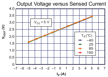
The calibration thing got me some headache. The ACS712 is a little special: Here is roughly the translation scheme between current and output voltage:
The default voltage is roughly at about 2,5V is there is no current at all. So the sensor must take this input voltage as zero reference. Unfortunately the ADS7828 is capped to 2,5V as a voltage reference by default, so it needs to be modified a little. Glad enough, you can use an external voltage reference. The Gravitech manual explains how to change the voltage reference so that the full 5V range can be activated. Unfortunately I am loosing half the dynamic range, which equals 2048 measurement values.
I am expecting 0,2V increase per Ampere, so I have 170 values available per 1 Ampere which gives me a measurement accuracy of about 0,01A, sounds sufficient in my case.
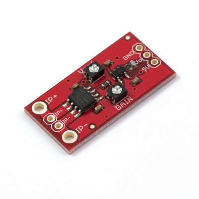
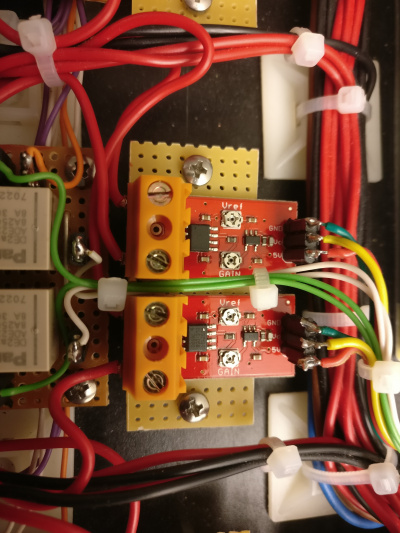
Unfortunately it turmed out that this is all crap. Since I wanted to have a more fine grained reading, I decided to get myself a bunch of Sparkfun Low Power Current Sensor breakouts:
https://www.sparkfun.com/products/8883
Paid a lot of money for them and understood that the Vref poti is so sensitive that you can hardly adjust it to a reference level of 1,00V or 0,50V. Playing around with the gain poti I understood that for a precise reading this no good either. Hard to adjust and the rise part of the reading is so steep that it is near to a rectangle signal. Maybe I was doing a mistake but lacking success I got impatient.
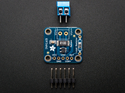
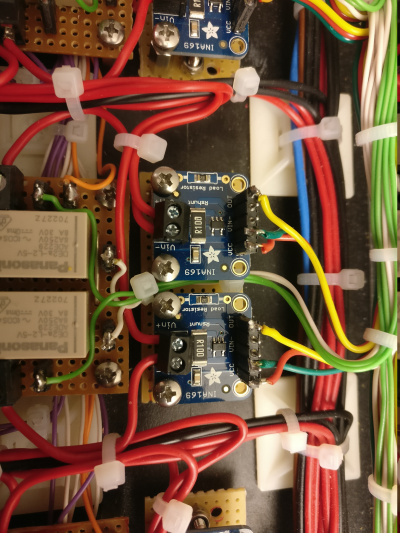
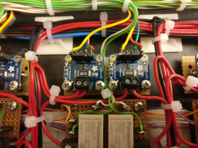
Result: Kicked it out again andgave a new try for another one: Here comes the Adafruit INA169:
https://www.adafruit.com/product/1164
For now I am content, but I understood that I must add a new resistor of let's say 20k so that I can display a rise of 1A into 2V. This will fit perfectly into the input range of 2,5V max of my I2C ADC, with a resolution of 4096 steps.
Outlook: Since I understood that there is a totally new set of current measurement chips, that can be used easily, I will use them in the future. The good side of them is that they can be read out using the I2C protocol, and they don't just give me the current but also the voltage.
- INA 219: https://www.adafruit.com/product/904 - only 26V and too few reserves for my 24V system, but with I2C
- INA 225: http://www.ti.com/lit/ds/sbos612a/sbos612a.pdf - 36V would fit fine.
Here is the result:
root@poeinjector:~# ./injcontrol.py
Pattern [87654321]  > 11111111
Temperature (c)     > 24.68
Pressure (hPa)      > 964.14
Humidity (%rel)     > 63.49
Current Channel  0  > 0     < (mA) > 0
Current Channel  1  > 1     < (mA) > 0
Current Channel  2  > 3     < (mA) > 0
Current Channel  3  > 0     < (mA) > 0
Current Channel  4  > 2     < (mA) > 0
Current Channel  5  > 0     < (mA) > 0
Current Channel  6  > 6     < (mA) > 0
Current Channel  7  > 7     < (mA) > 0
Voltage Channel  0  > 917   <  (V) > 11.86
Voltage Channel  1  > 916   <  (V) > 11.84
Voltage Channel  2  > 916   <  (V) > 11.84
Voltage Channel  3  > 917   <  (V) > 11.86
Voltage Channel  4  > 917   <  (V) > 11.86
Voltage Channel  5  > 917   <  (V) > 11.86
Voltage Channel  6  > 917   <  (V) > 11.86
Voltage Channel  7  > 918   <  (V) > 11.87
Fuse State       0  > OK
Fuse State       1  > OK
Fuse State       2  > OK
Fuse State       3  > OK
Fuse State       4  > OK
Fuse State       5  > OK
Fuse State       6  > OK
Fuse State       7  > OK
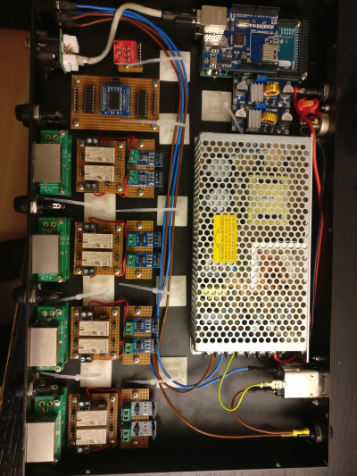
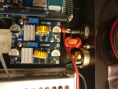
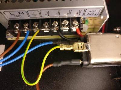
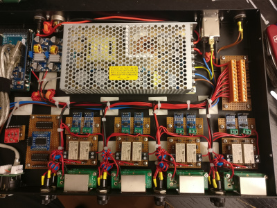
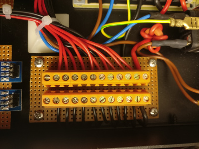
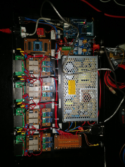
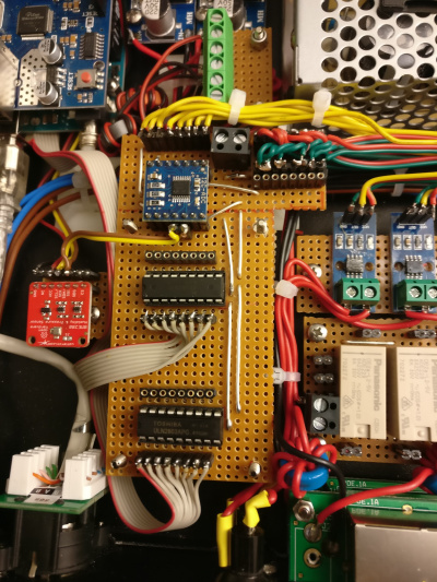
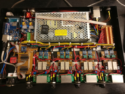
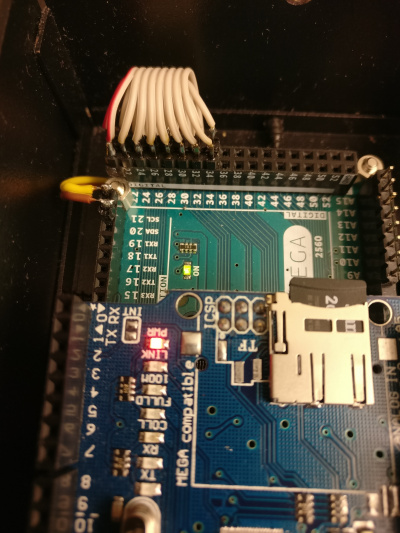
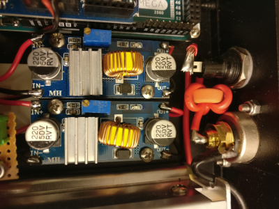
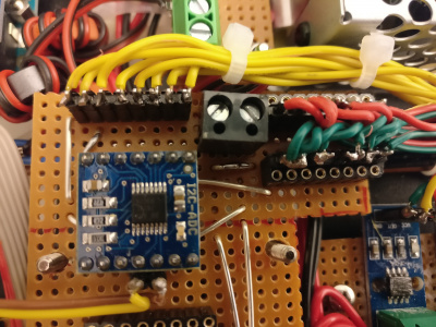
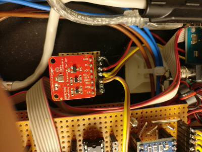
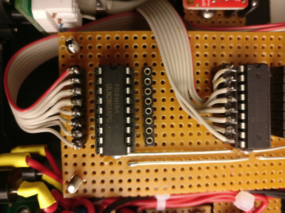
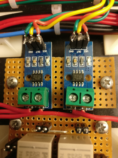
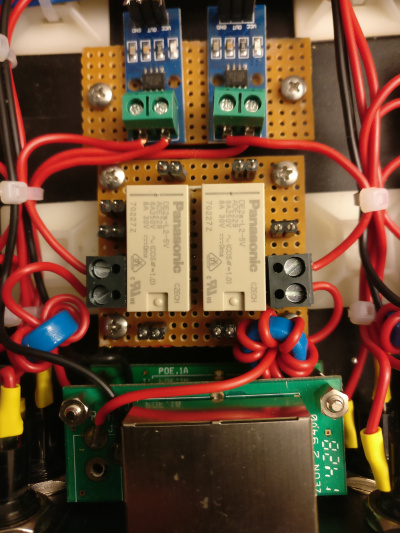
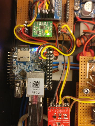
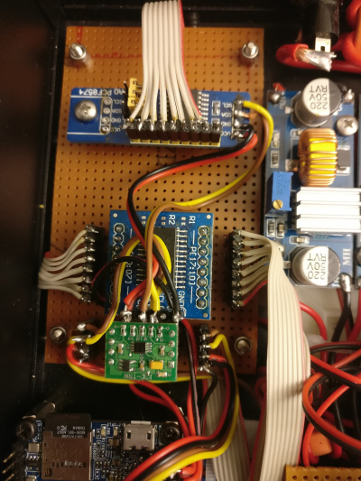
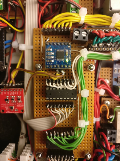
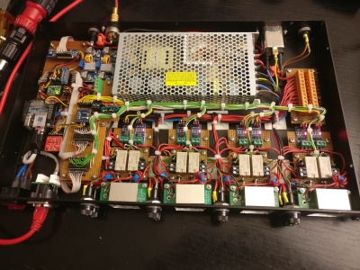
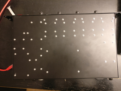
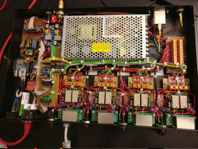
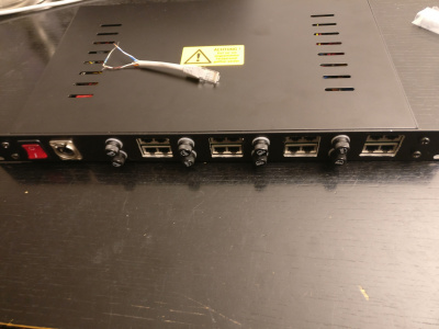
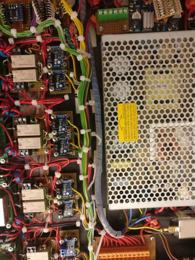
7 Project Progress and Images
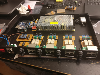
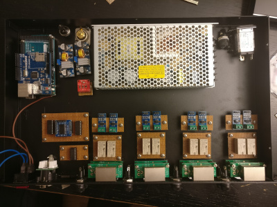
Trying to get a rough picture of the layout of the components.
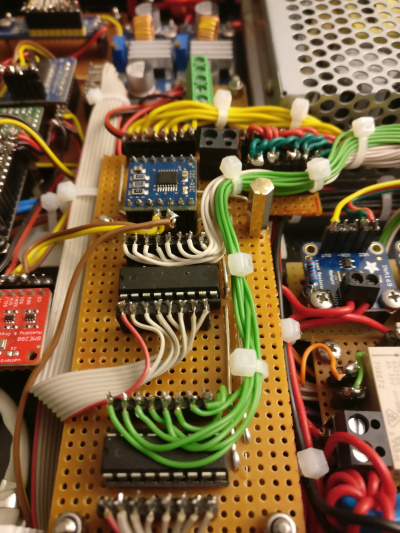
Drilling and cabling starts
Data cables installation...
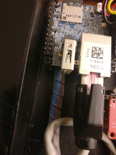
Now with the NanoPi Neo2:
Project seems finished!
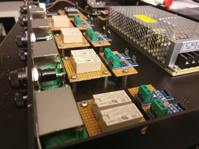
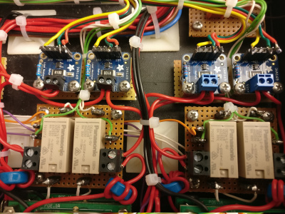
Nope, new insights. The blank ACS712 is crap. See above. Now with Sparkfun's ACS712 Low Current Sensor. But beware: I got rid of this solution also. The little Vref Poti's zero state does not correspond with a zero of the measurement, and it is practically impossible to set the Vref to an exact rating of let's say 1,00V. For this reason, I kicked them out again and found Lady Ada's Adafruit INA169 sensor instead. Let's see if it is a good solution.
After the installation of the INA169, everything works fine. Note that I removed the 10k SMD resistor and replaced it with a 20k resistor so 1A will produce a rise of 2V.
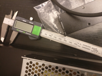
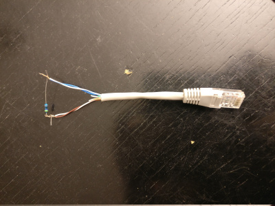
My calibration device: at 12V, a 470k resistor must produce a reading of 24mA. R=U/I :-) And to the right you can see the final setup.
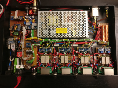
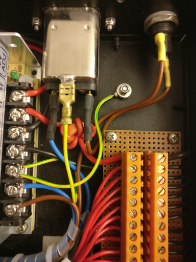
Definition of Done :-) Upon advice by DJ6PA I have added some extra grounding and some extra isolition of the high voltage cables from the low voltage cables so that my device agrees with VDE standards.
Finally in use:

