Setting up a 70cm AX25 based IP link
The goal of this project is to try out AX25 based IP networking, with the special challenge that the computing endpoints must be very efficient on power consumption. Since I have made good experiences with using ASUS WL-500gP routers operating OpenWRT, this IP link should be based on the same hardware. The AX25 based link is meant to act as a fallback link for the WIFI connection between DL8RDS and DB0MHB
Inhaltsverzeichnis
1 Hardware
1.1 DL8RDS side
- ASUS WL-500gP
- TNC2Multi
- (Transceiver still unclear)
1.2 DB0MHB side
- ASUS WL-500gP
- TNC2H
- T7F, 70cm highspeed data transceiver
2 Project phases
2.1 Building suitable cases
In my first attempt to work with ASUS WL-500gP hardware, unfortunately USB connections were destroyed due to excessive soldering temperature. Damn it, the PCB leads are so thin meanwhile, you can't really work with a normal 15 watts soldering iron any more. Since the router at DB0MHB is meant to steer some other radio devices over USB connections, I decided to invest some money in a new board and use the old board with the single USB socket on my side where I won't need to control any special radio hardware.
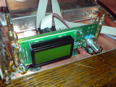
But given that I have consistent experience with PCB based case building in the meantime, the case for the new router is not so much of a challenge any more. The bigger challenge is to build a case for the T7F. I bought it just as a kit, which means that the core device is just contained in a little box with some pins coming out on the front side. On the pins you would plug the user interface, which again is just an open PCB board with a LCD display and a rotating switch mounted on it. As everything should go into a 15cmx10cmx5cm case and the user interface in front, I was to decide how to mount everything together. A short glance in my computer components assembly box told me that the little spacer mounting screws for mainboards are perfectly siuted to construct a fixing apparatus for the interface board. Here's a picture:
It is clear that the T7F above will work on the DB0MHB side. As of now, it is still unclear which transceiver technology will be used on my side. Since I bought another T7F without a GUI, I might give it a try again, since there's that OM Erich Linsmeier DL2RCG who has developed an enhanced T7F GUI. Let's see.
2.2 Getting all the connections right
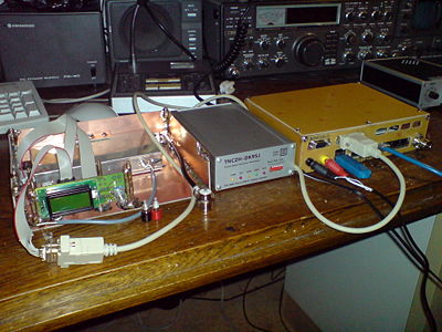
Making sure that all the plugs and sockets fit together the right way is always the most error prone activit, especially if it's all about digital lines: There's no "works a little better" but only "does work or does not". And it only works if you get multiple connections right at the same time. As of now, the front panel of the T7F is not yet ready, but here's already a good panorama of the DB0MHB station side:
The other side will look pretty much the same, except that the modem will be a TNC2Multi and the transceiver will look different. But in principle, the workings are identical.

