Playing with Filters: Unterschied zwischen den Versionen
Dl8rds (Diskussion | Beiträge) (→Building the Filter and Measurement setup) |
Dl8rds (Diskussion | Beiträge) |
||
| Zeile 8: | Zeile 8: | ||
https://www.buildcircuit.com/capacitors/ | https://www.buildcircuit.com/capacitors/ | ||
| + | |||
| + | == Books == | ||
| + | |||
| + | * M. Meyer. Signalverarbeitung. Analoge und digitale Signale, Systeme und Filter. Springer, 2017. https://www.amazon.de/Signalverarbeitung-Analoge-digitale-Signale-Systeme-ebook/dp/B00TSOQRY2 | ||
| + | * R. Unbehauen. Elektrische Netzwerke. Springer, 1987. https://www.springer.com/de/book/9783662001790 | ||
== Filter Theory == | == Filter Theory == | ||
Aktuelle Version vom 20. April 2019, 19:55 Uhr
Inhaltsverzeichnis
1 Scope
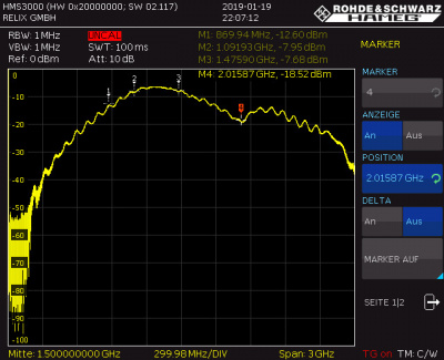
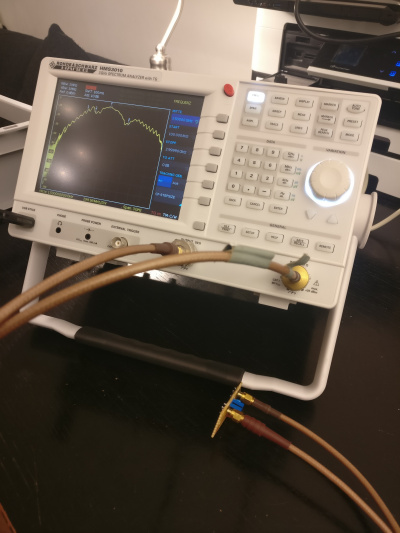
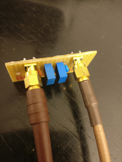
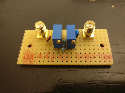
Well, the title of this page is "Playing with Filters". This is meant literally. So I just wanted to play around a little with my HAMEG HMS-3010 and see how I could build a bandpass and how to understand the steepness of the flanks.
The background was an idea to construct a bandpass for the frequency range mainly between 1090 MHz (ADS-B) and about 1300 MHz (23 cm band). I wanted to suppress the lower signals quite effectively, and thus maybe create a filter for GPS experiments at 1575 MHz.
Here is a link to a nice page on capacitors, which may be useful for some of you:
https://www.buildcircuit.com/capacitors/
2 Books
- M. Meyer. Signalverarbeitung. Analoge und digitale Signale, Systeme und Filter. Springer, 2017. https://www.amazon.de/Signalverarbeitung-Analoge-digitale-Signale-Systeme-ebook/dp/B00TSOQRY2
- R. Unbehauen. Elektrische Netzwerke. Springer, 1987. https://www.springer.com/de/book/9783662001790
3 Filter Theory
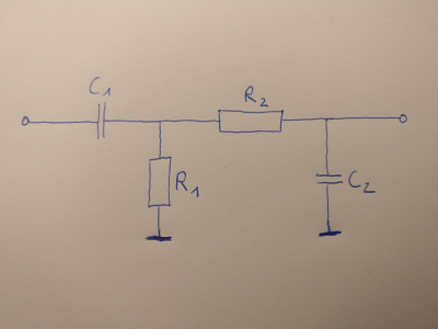
Generally, a bandpass consists of a high pass and a low pass that play together.
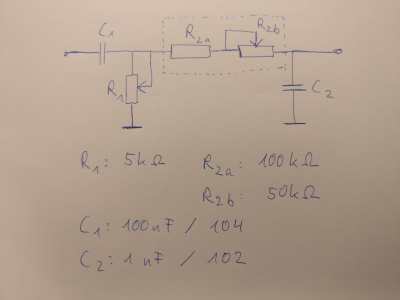
In order to optimise it a little, i decided to use potentiometers, and since I did not have a 150 kOhm type, I used a fixed value 100 kOhm plus a 50 kOhm poti in series.
