A remote Ethernet switch for my relay box
Aus DL8RDS Wiki
Inhaltsverzeichnis
1 Project Scope
The relay box I built recently is great, but without any physical switch a little hard to use. So the requirements profile is this:
- Must be usable through a web interface.
- Must be usable haprically through a physical switchboard.
- Must consume as little power as possible if not used.
- Must deactivate itself if unused.
- Must not change relay state if switched of or switched back on again.
- Must connect to the RaspberryPi that controls the relay box.
- Must retrieve the switch state when switched on.
- Must retrieve the switch state every 5 seconds.
2 Solution concept
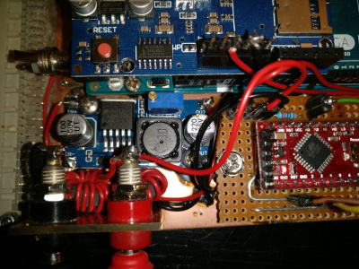
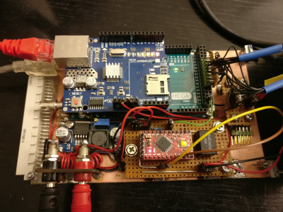
I am using two Arduinos:
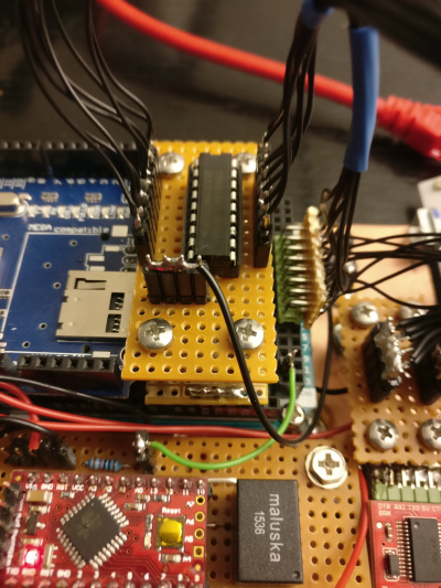
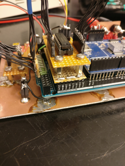
- Arduino Mega 2560 with Ethernet shield.
- The ethernet shield consumes quite much power and the ethernet chip is getting warm. So it must be switched off if not actively used.
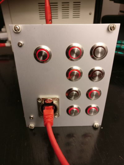
- The Arduino Mega provides enough GPIO pins to evaluate the switch state all the eight switches and control the red LED switchstate indicators.
- Arduino Pro Mini
- The ProMini is udes to control the entire switch board and consider inactivity times.
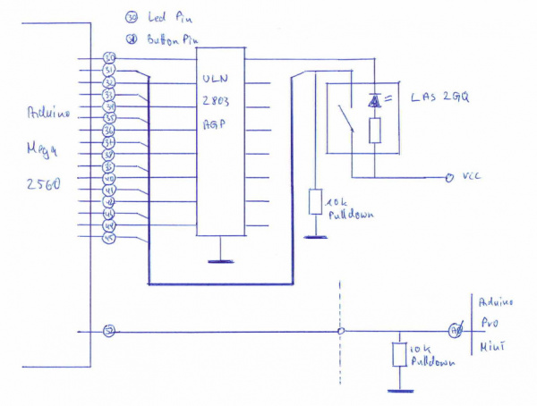
Both programs use the same debouncing algorithm, and the code of the Arduino ProMini is enhanced to consider an activity indicator that comes from the Arduino Mega. Whenever a switch is toggled, it sends a 50ms signal over to the ProMini so that the timeout watchdog is reset.
3 Components
Considerations and alternatives:
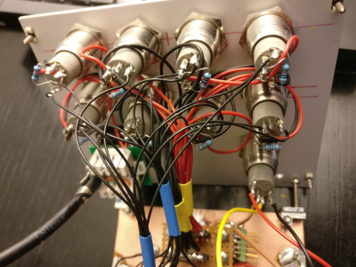
- The LAS2GQ button switch has a LED status indicator ring. The datasheet does not say anything about the LED resistor and its value. Only after I measured it and did some experiments, I found out that it seemed to work: A driver stage such as the ULN2803AGP Darlington transistor array seemed not necessary. Even though the max ratings of the GPIO pins are at 40mA, the required 52mA seem to work.
Components list:
- Arduino ProMini, 5€
- FTDI Basic USB programmer interface for the ProMini, 5€
- Arduino Mega, 32€
- Ethernet shield, 15€
- Neutrik Ethernet socket, 5€
- 9x LAS2GQ switches with red LED ring, 55€ https://www.reichelt.de/?ARTICLE=108416
- Datasheet: http://www.robotshop.com/media/files/PDF/datasheet-swt101a2b.pdf
- Note: The 12V version also works with 5V
- 8x 10k PullDown Resistors for the switches
- Aluminium panel, 10€
- Euro PCB 5€
- 64 pin backplane header
- DC-DC converter, 5€
- 2x ferrite cores, 5€
- 2x 4mm banana sockets for external power supply
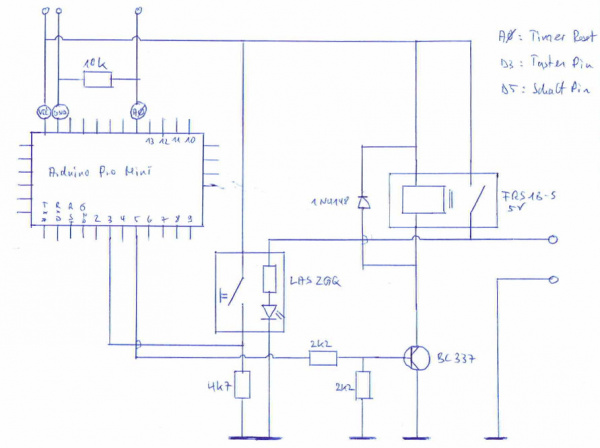
- Resistors 2k2, 2k2, 4k7, 10k
- Diode 1N4148
- Relay FRS1B-S 5V, 5€
The values are rounded. Total costs: 150€
4 Schema
4.1 Arduino ProMini
4.2 Arduino Mega
5 Operational observations
- Max power consumption: 2,68W
- Standby power consumption: 134mW
- Max input voltage: 30V
6 Code
6.1 Arduino ProMini
// constants won't change. They're used here to
// set pin numbers:
const int buttonPin = 3;    // the number of the pushbutton pin
const int ledPin = 5;      // the number of the LED pin
const int externSwitchInput = 0;

// Variables will change:
int ledState = LOW;         // the current state of the output pin
int buttonState;             // the current reading from the input pin
int lastButtonState = HIGH;   // the previous reading from the input pin

// the following variables are unsigned long's because the time, measured in miliseconds,
// will quickly become a bigger number than can be stored in an int.
unsigned long lastDebounceTime = 0;  // the last time the output pin was toggled
unsigned long debounceDelay = 50;    // the debounce time; increase if the output flickers
unsigned long lastSwitchTime = 0;
unsigned int inactivityTime = 20000;  // milliseconds since last activity

void setup() {
  Serial.begin(9600);
  pinMode(buttonPin, INPUT);
  pinMode(ledPin, OUTPUT);

  // set initial LED state
  digitalWrite(ledPin, ledState);

}

void loop() {
  // read the state of the switch into a local variable:
  int reading = digitalRead(buttonPin);
  int remoteSwitchEvent = analogRead(externSwitchInput);

  // remote activity
  if (remoteSwitchEvent > 512u) {
    Serial.print("Tastendruck extern zum Zeitpunkt>");
    Serial.println(millis(), DEC);
    lastSwitchTime = millis();
  }

  // switch off because of inactivity

  if (ledState == HIGH && (millis() - lastSwitchTime > inactivityTime)) {
    Serial.print("Millis >");
    Serial.println(millis());
    Serial.print("LastSwitchTime >");
    Serial.println(lastSwitchTime);
    Serial.print("millis() - lastSwitchTime >");
    Serial.println(millis() - lastSwitchTime);
    Serial.print("Inactivity Time >");
    Serial.println(inactivityTime);
    Serial.println("Timeout");
    ledState = LOW;
    lastButtonState = HIGH;
    lastSwitchTime = 0;
  }

  // check to see if you just pressed the button
  // (i.e. the input went from LOW to HIGH),  and you've waited
  // long enough since the last press to ignore any noise:

  // If the switch changed, due to noise or pressing:
  if (reading != lastButtonState) {
    // reset the debouncing timer
    lastDebounceTime = millis();
  }

  if ((millis() - lastDebounceTime) > debounceDelay) {
    // whatever the reading is at, it's been there for longer
    // than the debounce delay, so take it as the actual current state:

    // if the button state has changed:
    if (reading != buttonState) {
      buttonState = reading;

      // only toggle the LED if the new button state is HIGH
      if (buttonState == HIGH) {
        ledState = !ledState;
        lastSwitchTime = millis();
        Serial.println("Switch Event");
      }
    }
  }

  // set the LED:
  digitalWrite(ledPin, ledState);

  // save the reading.  Next time through the loop,
  // it'll be the lastButtonState:
  lastButtonState = reading;
}
6.2 Arduino Mega 2560
